Menu 6
Parameter
structure
Keypad and
display
Parameter
x.00
Parameter
description format
Advanced parameter
descriptions
Macros
Serial comms
protocol
Electronic
nameplate
Performance RFC mode
136 Unidrive SP Advanced User Guide
www.controltechniques.com Issue Number: 10
1: Stop
Open-loop
The action taken by the drive is the same as for ride through mode, except the ramp down rate is at least as fast as the deceleration ramp setting and
the drive will continue to decelerate and stop even if the mains is re-applied. If normal or timed injection braking is selected the drive will use ramp
mode to stop on loss of the supply. If ramp stop followed by injection braking is selected, the drive will ramp to a stop and then attempt to apply DC
injection. If the main is reapplied the drive restarts after it reaches the ready state provided the necessary controls are still active to initiate a start.
Closed-loop vector or Servo
The speed reference is set to zero and the ramps are disabled allowing the drive to decelerate the motor to a stop under current limit. If the mains is
re-applied while the motor is stopping any run signal is ignored until the motor has stopped. If the current limit value is set at a very low level the drive
may trip UU before the motor has stopped. If the mains is reapplied the drive restarts after it reaches the ready state provided the necessary controls
are still active to initiate a start.
2: ride.th
The drive detects mains loss when the DC bus voltage falls below Vml
1
. The drive then enters a mode where a closed-loop controller attempts to hold
the DC bus level at Vml
2
. This causes the motor to decelerate at a rate that increases as the speed falls. If the mains is re-applied it will force the DC
bus voltage above the detection threshold Vml
3
and the drive will continue to operate normally. The output of the mains loss controller is a current
demand that is fed into the current control system and therefore the gain parameters Pr 4.13 and Pr 4.14 must be set up for optimum control. See
Pr 4.13 and Pr 4.14 on page 103 for set-up details.
The following table shows the voltage levels used by drives with each voltage rating.
* Vml
1
is defined by Pr 6.48. The values given in the table are the default values.
This parameter is provided to allow the user to select several predefined digital input routing macros to control the sequencer. When a value between
0 and 3 is selected, the drive processor continuously updates the destination parameters for digital I/O T25, T26 and T27, and the enable sequencer
latching bit (Pr 6.40). When a value of 4 is selected the destination parameters for these digital I/O and Pr 6.40 can be modified by the user. (Note any
changes made to the destination parameters only become active after a drive reset).
If Pr 6.04 has been set to a value of 0 to 3, then setting Pr 6.04 to 4 does not automatically reconfigure terminals T25, T26 and T27 to their default
functions. To return terminals T25, T26 and T27 to their default functions, one of the following operations should be performed.
• Drive defaults should be restored. See section 5.8 Restoring parameter defaults in the Unidrive SP User Guide for details.
• Manually set Pr 6.04 to 4, Pr 6.40 to 0, Pr 8.22 to 10.33, Pr 8.23 to 6.30, and Pr 8.24 to 6.32.
* With software version V01.10.00 and later, Pr 6.29 can be used as a fast disable parameter. See Pr 6.29 on page 142 for more information.
Pr 6.29 reflects the state of the secure disable input and so it is not necessary to control this with a digital input, but the set up here is provided for
older products. Routing a digital input can be used for fast disabling, see Pr 6.29 for more details.
Voltage level 200V drive 400V drive 575V drive 690V drive
Vuu 175 330 435 435
Vml
1
205* 410* 540* 540*
Vml
2
Vml
1
- 10V Vml
1
- 20V Vml
1
- 25V Vml
1
- 25V
Vml
3
Vml
1
+ 10 Vml
1
+ 15 Vml
1
+ 50 Vml
1
+ 50
Vuu Restart 215 425 590 590
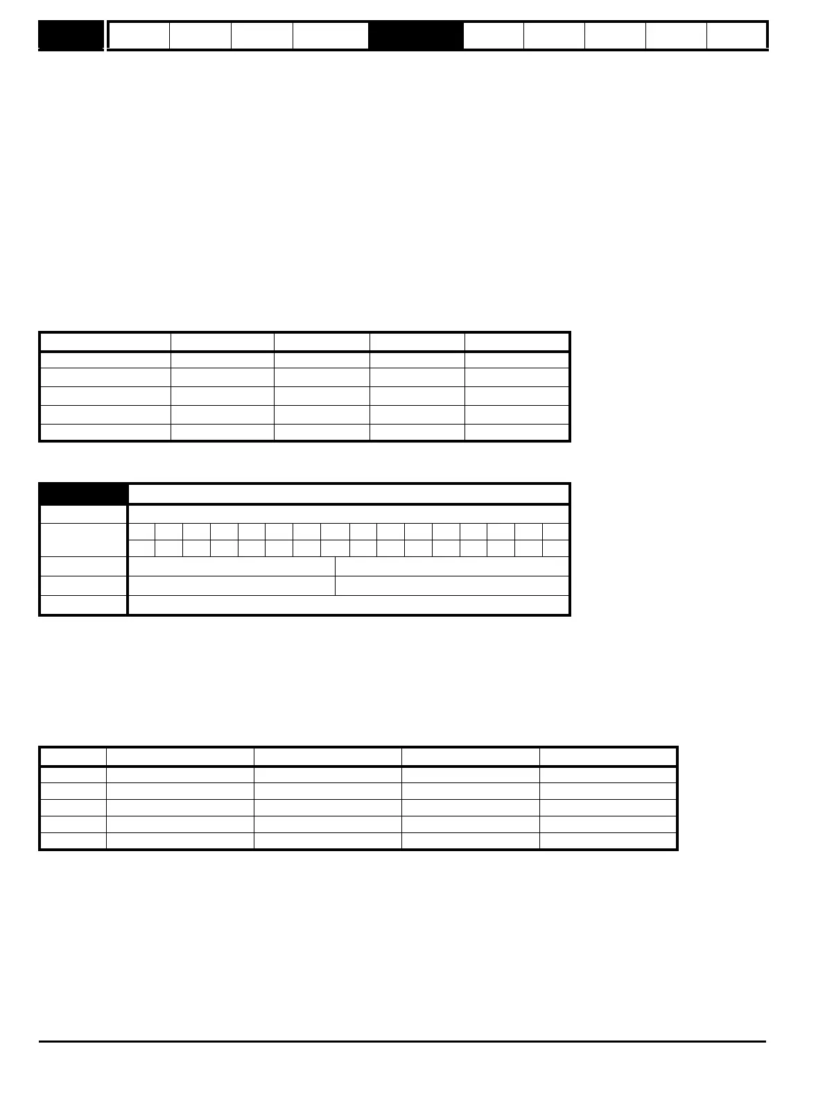
6.04 Start/stop logic select
Drive modes Open-loop, Closed-loop vector, Servo
Coding
BitSP FI DETEVMDPNDRANCNVPTUSRWBUPS
111
Range Open-loop, Closed-loop vector, Servo 0 to 4
Default Open-loop, Closed-loop vector, Servo 4
Update rate Background read
Pr 6.04 T25 (Pr 8.22) T26 (Pr 8.23) T27 (Pr 8.24) Pr 6.40
0Pr 6.29* Pr 6.30 Run Forward Pr 6.32 Run Reverse 0 (non latching)
1Pr 6.39 Not stop Pr 6.30 Run Forward Pr 6.32 Run Reverse 1 (latching)
2Pr 6.29* Pr 6.34 Run Pr 6.33 Fwd /Rev 0 (non latching)
3Pr 6.39 Not stop Pr 6.34 Run Pr 6.33 Fwd/Rev 1 (latching)
4 User prog User prog User prog User prog

 Loading...


