Parameter
structure
Keypad and
display
Parameter
x.00
Parameter
description format
Advanced parameter
descriptions
Macros
Serial comms
protocol
Electronic
nameplate
Performance RFC mode
Menu 4
Unidrive SP Advanced User Guide 103
Issue Number: 10 www.controltechniques.com
Open-loop
These parameters control the proportional and integral gains of the current controller used in the open loop drive. As already mentioned the current
controller either provides current limits or closed loop torque control by modifying the drive output frequency. The control loop is also used in its torque
mode during mains loss, or when the controlled mode standard ramp is active and the drive is decelerating, to regulate the flow of current into the
drive. Although the default settings have been chosen to give suitable gains for less demanding applications it may be necessary for the user to adjust
the performance of the controller. The following is a guide to setting the gains for different applications.
Current limit operation
The current limits will normally operate with an integral term only, particularly below the point where field weakening begins. The proportional term is
inherent in the loop. The integral term must be increased enough to counter the effect of the ramp which is still active even in current limit. For
example, if the drive is operating at constant frequency and is overloaded the current limit system will try to reduce the output frequency to reduce the
load. At the same time the ramp will try to increase the frequency back up to the demand level. If the integral gain is increased too far the first signs of
instability will occur when operating around the point where field weakening begins. These oscillations can be reduced by increasing the proportional
gain. A system has been included to prevent regulation because of the opposite actions of the ramps and the current limit. This can reduce the actual
level that the current limit becomes active by 12.5%. This still allows the current to increase up to the current limit set by the user. However the current
limit flag (Pr 10.09) could become active up to 12.5% below the current limit depending on the ramp rate used.
Torque control
Again the controller will normally operate with an integral term only, particularly below the point where field weakening begins. The first signs of
instability will appear around base speed, and can be reduced by increasing the proportional gain. The controller can be less stable in torque control
mode rather than when it is used for current limiting. This is because load helps to stabilise the controller, and under torque control the drive may
operate with light load. Under current limit the drive is often under heavy load unless the current limits are set at a low level.
Mains loss and controlled standard ramp
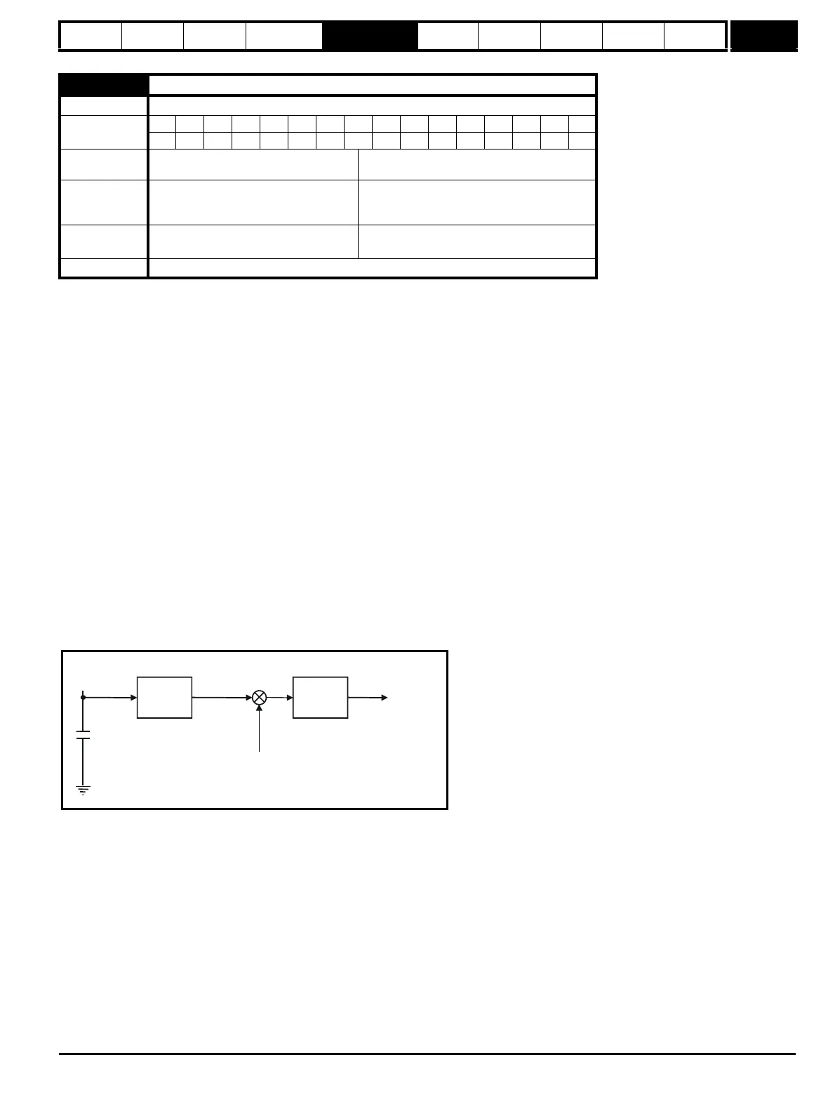
The DC bus voltage controller becomes active if mains loss detection is enabled and the drive supply is lost or controlled standard ramp is being used
and the machine is regenerating. The DC bus controller attempts to hold the DC bus voltage at a fixed level by controlling the flow of current from the
drive inverter into its DC bus capacitors. The output of the DC bus controller is a current demand which is fed into the current PI controller as shown
in the following diagram.
Although it is not usually necessary the DC bus voltage controller can be adjusted with Pr 5.31. However, it may often be necessary to adjust the
current controller gains to obtain the required performance. If the gains are not suitable it is best to set up the drive in torque control first. Set the gains
to a value that does not cause instability around the point at which field weakening occurs. Then revert back to open loop speed control in standard
ramp mode. To test the controller the supply should be removed while the motor is running. It is likely that the gains can be increased further if
required because the DC bus voltage controller has a stabilising effect, provided that the drive is not required to operate in torque control mode.
4.14 Current controller Ki gain
Drive modes Open-loop, Closed-loop vector, Servo, Regen
Coding
Bit SP FI DE Txt VM DP ND RA NC NV PT US RW BU PS
111
Range
Open-loop, Closed-loop vector, Servo,
Regen
0 to 30,000
Default
Drive voltage rating:
Open-loop,
Closed-loop vector, Servo, Regen
200V 400V 575V 690V
40 40 40 40
1,000 2,000 2,400 3,000
Second motor
parameter
Closed-loop vector, Servo Pr 21.23
Update rate Background read
DC Bus
voltage
controller
P Pr
4.13
I Pr
4.14
Frequency
reference
Active current
DC Bus
capacitor
Current
demand

 Loading...


