Parameter
structure
Keypad and
display
Parameter
x.00
Parameter
description format
Advanced parameter
descriptions
Macros
Serial comms
protocol
Electronic
nameplate
Performance RFC mode
Menu 11
Unidrive SP Advanced User Guide 205
Issue Number: 10 www.controltechniques.com
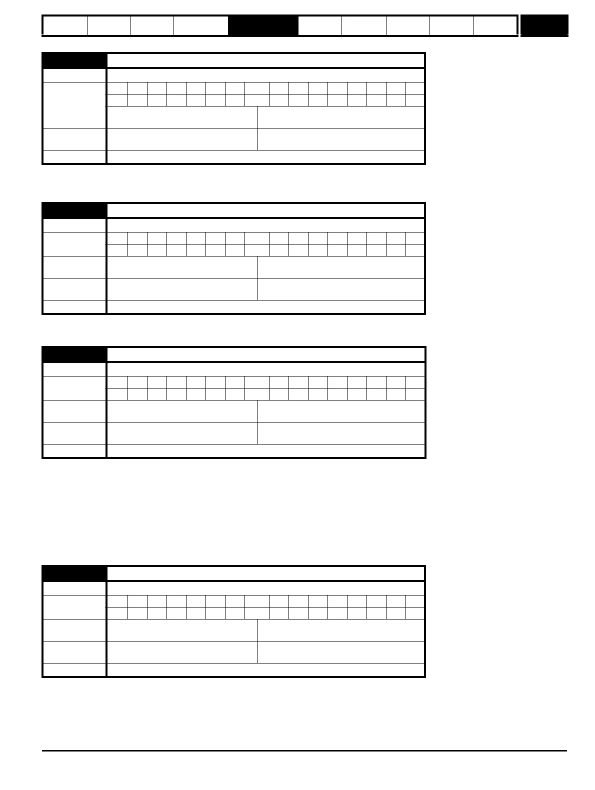
This parameter may be used to scale the value of Pr 0.30 seen via the LED keypad (not via serial comms). Any parameter routed to Pr 0.30 may be
scaled. Scaling is only applied in the status and view modes. If the parameter is edited via the keypad it reverts to its un-scaled value during editing.
This parameter defines which menu 0 parameter is displayed on power-up.
Used to define the unique address for the drive for the serial interface. The drive is always a slave.
ANSI
When the ANSI protocol is used the first digit is the group and the second digit is the address within a group. The maximum permitted group number
is 9 and the maximum permitted address within a group is 9. Therefore, Pr 11.23 is limited to 99 in this mode. The value 00 is used to globally address
all slaves on the system, and x0 is used to address all slaves of group x, therefore these addresses should not be set in this parameter.
Modbus RTU
When the Modbus RTU protocol is used addresses between 0 and 247 are permitted. Address 0 is used to globally address all slaves, and so this
address should not be set in this parameter.
This parameter defines the communications protocol used by the 485 comms port on the drive. This parameter can be changed via the drive keypad,
via a Solutions Module or via the comms interface itself. If it is changed via the comms interface, the response to the command uses the original
protocol. The master should wait at least 20ms before sending a new message using the new protocol. (Note: ANSI uses 7 data bits, 1 stop bit and
even parity; Modbus RTU uses 8 data bits, 2 stops bits and no parity).
11.21 Parameter 0.30 scaling
Drive modes Open-loop, Closed-loop vector, Servo, Regen
Coding
Range
Bit SP FI DE Txt VM DP ND RA NC NV PT US RW BU PS
3 111
Open-loop, Closed-loop vector, Servo,
Regen
0.000 to 9.999
Default
Open-loop, Closed-loop vector, Servo,
Regen
1.000
Update rate Background read
11.22 Parameter displayed at power-up
Drive modes Open-loop, Closed-loop vector, Servo, Regen
Coding
Bit SP FI DE Txt VM DP ND RA NC NV PT US RW BU PS
2 1111
Range
Open-loop, Closed-loop vector, Servo,
Regen
Pr 0.00 to Pr 0.59
Default
Open-loop, Closed-loop vector, Servo
Regen
Pr 0.10
Pr 0.11
Update rate Background read
11.23 Serial address
Drive modes Open-loop, Closed-loop vector, Servo, Regen
Coding
Bit SP FI DE Txt VM DP ND RA NC NV PT US RW BU PS
111
Range
Open-loop, Closed-loop vector, Servo,
Regen
00 to 247
Default
Open-loop, Closed-loop vector, Servo,
Regen
1
Update rate Background read
11.24 Serial mode
Drive modes Open-loop, Closed-loop vector, Servo, Regen
Coding
Bit SP FI DE Txt VM DP ND RA NC NV PT US RW BU PS
1 111
Range
Open-loop, Closed-loop vector, Servo,
Regen
0 to 2
Default
Open-loop, Closed-loop vector, Servo,
Regen
1
Update rate Background read

 Loading...


