Parameter
structure
Keypad and
display
Parameter
x.00
Parameter
description format
Advanced parameter
descriptions
Macros
Serial comms
protocol
Electronic
nameplate
Performance RFC mode
Menu 5
Unidrive SP Advanced User Guide 113
Issue Number: 10 www.controltechniques.com
Open-loop
Although the range for scaling purposes is ±SPEED_FREQ_MAX, the actual parameter value can be increased beyond this range by slip
compensation. This parameter gives the output frequency of the drive, i.e. the sum of the post ramp reference and the slip compensation.
Closed-loop vector and Servo
In these modes the output frequency is not controlled directly, and so the output frequency displayed in this parameter is calculated by measuring the
frequency of the controller reference frame.
Regen
In Regen mode the supply frequency is shown. Negative values indicate negative phase rotation of the supply.
This is the modulus of the r.m.s. line to line voltage at the inverter output at the drive output frequency.
Open-loop, Closed-loop vector and Servo modes
The output power is the dot product of the output voltage and current vectors. Positive power indicates power flowing from the drive to the motor
(motoring) and negative power indicates power flowing from the motor to the drive (regen).
Regen mode
The output power is the dot product of the output voltage and current vectors. Positive power indicates power flowing from the supply to the drive, and
negative power indicates power flowing from the drive to the supply.
The motor rpm is calculated from the post ramp reference (Pr 2.01) for normal operation, or the slave frequency demand (Pr 3.01) if frequency slaving
is being used. The speed of rotation is calculated as follows:
rpm = 60 x frequency / no. of pole pairs
This calculation relies on the number of motor poles being set up correctly in Pr 5.11, or if auto mode is selected (Pr 5.11 = 0) then it relies on a
reasonably accurate value of motor rated speed being set in Pr 5.08 to allow correct calculation of the motor poles. If frequency slaving is being used
there will be an error due to the slip frequency. However, in normal operation the result will be reasonably accurate provided that the slip
compensation has been set up correctly in the rated full load rpm parameter (Pr 5.08).
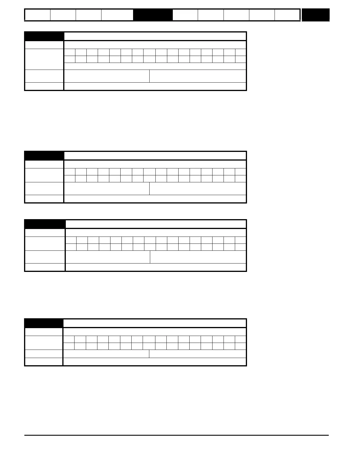
5.01 Output frequency
Drive modes Open-loop, Closed-loop vector
Coding
Bit SP FI DE Txt VM DP ND RA NC NV PT US RW BU PS
111111
RFC: VM = 0
Range
Open-loop
RFC
±SPEED_FREQ_MAX Hz
±1250.0 Hz
Update rate 250μs write
5.02 Output voltage
Drive modes Open-loop, Closed-loop vector
Coding
Bit SP FI DE Txt VM DP ND RA NC NV PT US RW BU PS
11111
Range
Open-loop, Closed-loop vector, Servo,
Regen
0 to AC_VOLTAGE_MAX V
Update rate Background write
5.03 Output power
Drive modes Open-loop, Closed-loop vector, Servo, Regen
Coding
Bit SP FI DE Txt VM DP ND RA NC NV PT US RW BU PS
112111
Range
Open-loop, Closed-loop vector, Servo,
Regen
±POWER_MAX kW
Update rate Background write
5.04 Motor rpm
Drive modes Open-loop
Coding
Bit SP FI DE Txt VM DP ND RA NC NV PT US RW BU PS
1111
Range Open-loop ±180,000 rpm
Update rate Background write

 Loading...


