Menu 3
Closed-loop
Parameter
structure
Keypad and
display
Parameter
x.00
Parameter
description format
Advanced parameter
descriptions
Macros
Serial comms
protocol
Electronic
nameplate
Performance RFC mode
58 Unidrive SP Advanced User Guide
www.controltechniques.com Issue Number: 10
This is the final speed demand at the input to the speed regulator formed by the sum of the ramp output and the hard speed reference (if the hard
speed reference is enabled). If the drive is disabled this parameter will show 0.0.
The speed feedback can be taken from the drive encoder port or a position feedback module installed in any slot as selected with Pr 3.26. Pr 3.02
shows the level of the speed feedback selected for the speed controller. The FI attribute is set for this parameter, so display filtering is active when this
parameter is viewed with one of the drive keypads. The value held in the drive parameter (accessible via comms or a Solutions Module) does not
include this filter, but is a value that is obtained over a sliding 16ms period to limit the ripple seen in this parameter value. The speed feedback value
includes encoder quantization ripple given by the following equation:
Ripple in Pr 3.02 = 60 / 16ms / (ELPR x 4)
where ELPR is the equivalent encoder lines per revolution as defined below.
For example a 4096 line Ab type encoder gives a ripple level of 0.23rpm.
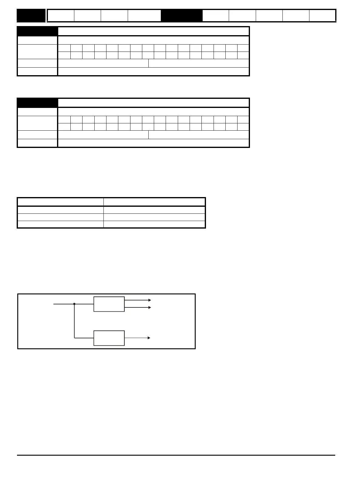
The 16ms sliding window filter is always applied to the value shown in Pr 3.02, but this sliding window filter is not normally applied to the actual speed
feedback used by the speed controller or the drive encoder reference system (Pr 3.43 to Pr 3.46).The user may apply a filter to the speed controller
input and the drive encoder reference system input if required by setting Pr 3.42 to the required filter time. The encoder ripple seen by the speed
controller is given by:
Encoder speed ripple = 60 / Filter time / (ELPR x 4)
If Pr 3.42 is set to zero (no filter) the ripple seen by the speed controller and drive encoder reference system is given by:
Encoder speed ripple = 60 / 250μs / (ELPR x 4)
The diagram above shows the filter arrangement. It should be noted that the same filtering is provided at the speed controller input and for Pr 3.02
when the feedback is obtained from a Solutions Module, but the variable length window filter is controlled by Pr x.19.
It is not advisable to use the speed feedback filter unless it is specifically required for high inertia applications with high controller gains, or if a
commutation signal only encoder is used, because the filter has a non-linear transfer function. It is preferable to use the current demand filters (see Pr
4.12 or 4.23) as these are linear first order filters that provide filtering on noise generated from both the speed reference and the speed feedback. It
should be noted that any filtering included within the speed controller feedback loop, either on the speed feedback or the current demand, introduces
a delay and limits the maximum bandwidth of the controller for stable operation.
The speed ripple can be quite high, for example with a 4096 line encoder the speed ripple is 14.6rpm, but this does not define the resolution of the
speed feedback which is normally much better and depends on the length of the measuring period used to obtain the feedback. This is shown in the
improved resolution of the value accessible in Pr 3.02 which is measured over 16ms, i.e. a resolution of 0.23rpm with a 4096 line encoder. The speed
controller itself accumulates all pulses from the encoder, and so the speed controller resolution is not limited by the feedbac
k, but by the resolution of
the speed reference. If a SINCOS encoder is used the encoder speed ripple is reduced by a factor of 2
(
2 - INTERPOLATION BITS)
For example with the
nominal 10 bits of interpolation information, the speed ripple is reduced by a factor of 256. This shows how a SINCOS encoder can reduce noise
caused by encoder quantization without any filtering in the speed feedback or the current demand, so that high gains may be used to give high
dynamic performance and a very stiff system.
3.01 Final speed reference
Drive modes Closed-loop vector, Servo
Coding
Bit SP FI DE Txt VM DP ND RA NC NV PT US RW BU PS
1 11111
Range Closed-loop vector, Servo ±SPEED_MAX rpm
Update rate 4ms write
3.02 Speed Feedback
Drive modes Closed-loop vector, Servo
Coding
Bit SP FI DE Txt VM DP ND RA NC NV PT US RW BU PS
1 11111
Range Closed-loop vector, Servo ±SPEED_MAX rpm
Update rate 4ms write
Position feedback device ELPR
Ab, Ab.Servo number of lines per revolution
Fd, Fr, Fd.Servo, Fr.Servo number of lines per revolution / 2
SC.Hiper, SC.EnDat, SC, SC.SSI number of sine waves per revolution
Speed controller
Drive encoder
reference system
Filter defined
by Pr
3.42
16ms filter
Pr and Pr
3.02 3.27
From the drive
encoder port

 Loading...


