EasyManua.ls Logo

Emerson unidrive sp User Manual

Emerson unidrive sp
420 pages
To Next Page IconTo Next Page
To Previous Page IconTo Previous Page
Page #18 background imageLoading...
Page #18 background image
Parameter
structure
Keypad and
display
Parameter x.00
Parameter
description format
Advanced parameter
descriptions
Macros
Serial comms
protocol
Electronic
nameplate
Performance RFC mode
18 Unidrive SP Advanced User Guide
www.controltechniques.com Issue Number: 10
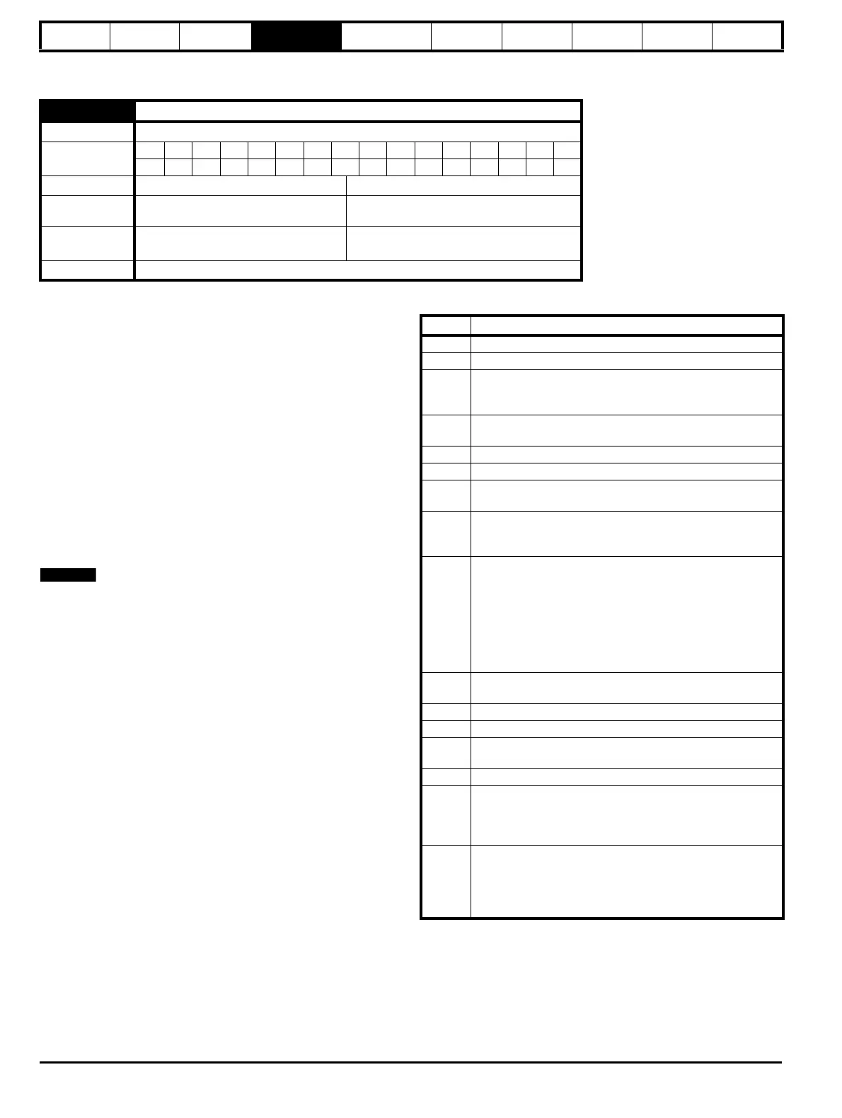
4 Parameter description format
In the following sections descriptions are given for the advanced parameter set. With each parameter the following information block is given.
The top row gives the menu parameter number and name. The other
rows provide the following information.
Drive modes
The drive modes are the modes in which this parameter is accessible. If
the parameter is not present the parameter is skipped when accessing
from the keypad. The following types are possible.
Open-loop - The control strategy is V/F mode with fixed boost or open-
loop vector control.
Closed-loop vector - The control strategy is rotor flux oriented vector
control with closed-loop current operation for induction motors. The drive
can be operated with or without position feedback.
Servo - The control strategy is rotor flux oriented vector control with
closed-loop current operation for permanent magnet synchronous
motors. The drive must be operated with position feedback.
Regen - The drive operates as a PWM rectifier.
Coding
This guide will show all bit parameters (with the Bit coding), as having a
parameter range of "0 to 1", and a default value of either "0" or "1". This
reflects the value seen through serial communications. The bit
parameters will be displayed on the SM-Keypad or SM-Keypad Plus (if
used) as being "OFF" or "On" ("OFF"= 0, "On" = 1).
The coding defines the attributes of the parameter as follows:
5.11 Number of motor poles
Drive modes
Open-loop, Closed-loop vector, Servo
Coding
Bit SP FI DE Txt VM DP ND RA NC NV PT US RW BU PS
1111
Range Open-loop, Closed-loop vector, Servo 0 to 60 (Auto to 120 POLE)
Default
Open-loop, Closed-loop vector
Servo
0 (Auto)
3 (6 POLE)
Second motor
parameter
Open-loop, Closed-loop vector, Servo Pr 21.11
Update rate
Background read
NOTE
Coding Attribute
Bit 1 bit parameter
SP Spare: not used
FI
Filtered: some parameters which can have rapidly changing
values are filtered when displayed on the drive keypad for
easy viewing.
DE
Destination: indicates that this parameter can be a
destination parameter.
Txt Text: the parameter uses text strings instead of numbers.
VM Variable maximum: the maximum of this parameter can vary.
DP
Decimal place: indicates the number of decimal places used
by this parameter.
ND
No default: when defaults are loaded (except when the drive
is manufactured or on EEPROM failure) this parameter is not
modified.
RA
Rating dependent: this parameter is likely to have different
values and ranges with drives of different voltage and current
ratings. Parameters with this attribute will not be transferred
to the destination drive by SMARTCARDs when the rating of
the destination drive is different from the source drive and the
file is a parameter file. However, with software V01.09.00 and
later the value will be transferred if only the current rating is
different and the file is a differences from default type file.
NC
Not copied: not transferred to or from SMARTCARDs during
copying.
NV Not visible: not visible on the keypad.
PT Protected: cannot be used as a destination.
US
User save: saved in drive EEPROM when the user initiates a
parameter save.
RW Read/write: can be written by the user.
BU
Bit default one/unsigned: Bit parameters with this flag set to
one have a default of one (all other bit parameters have a
default of zero. Non-bit parameters are unipolar if this flag is
one.
PS
Power-down save: parameter automatically saved in drive
EEPROM when the under volts (UV) trip occurs.
With software version V01.08.00 and later, power-down
save parameters are also saved in the drive when the user
initiates a parameter save.

Table of Contents

Question and Answer IconNeed help?

Do you have a question about the Emerson unidrive sp and is the answer not in the manual?

Emerson unidrive sp Specifications

General IconGeneral
TypeAC Drive
Storage Temperature-40°C to +70°C
Communication OptionsCANopen, Ethernet, Profibus, DeviceNet
Safety FeaturesSafe Torque Off (STO), Safe Stop 1 (SS1), Safe Operating Stop (SOS)
Overload150% for 60 seconds
EnclosureIP20
Output Voltage Range0 - Input Voltage
Protection FeaturesOvercurrent, Overvoltage, Undervoltage, Short Circuit
Humidity95% non-condensing
Cooling MethodFan cooled
DimensionsVaries depending on the power rating and enclosure type
WeightVaries depending on the power rating and enclosure type
Input Voltage200 VAC - 690 VAC ±10%

Summary

Parameter structure

1.1 Menu 0

Describes Menu 0, its fixed and programmable parameters, and its relation to other menus.

1.2 Advanced menus

Explains the purpose and accessibility of advanced menus for specific drive features.

Keypad and display

2.1 Understanding the display

Explains the SM-Keypad and SM-Keypad Plus displays, including their features and layout.

2.2 Keypad operation

Details the operation of the keypad controls, including the joypad, mode, and control buttons.

2.4 Parameter view mode

Explains navigation between parameters and menus, and displaying parameter values.

2.5 Edit mode

Details how to enter Edit Mode and modify parameter values using the keypad, including digit selection.

Parameter x.00

3.2 Saving parameters in drive EEPROM

Details the process of saving parameters to EEPROM using Pr x.00, emphasizing data loss risk and features.

3.3 Loading defaults

Explains how to load default drive parameters, including the implications for user-saved parameters.

3.4 SMARTCARD transfers

Describes transferring parameters, setup macros, and ladder programs to/from SMARTCARDs.

Parameter description format

4.1 Parameter ranges and variable maximums:

Defines parameter ranges and variable maximums, which can depend on other parameters, drive rating, or drive mode.

Advanced parameter descriptions

5.2 Feature look-up table

Presents a comprehensive table linking features to their corresponding parameter numbers for easy reference.

Menu 1: Frequency/speed reference

1.06 Maximum reference clamp

Defines the maximum speed (closed-loop mode) or frequency (open-loop mode) reference.

1.10 Bipolar reference enable

Enables or disables bipolar reference, affecting how the reference value is interpreted.

1.15 Preset selector

Defines how preset references are selected based on digital inputs and the value of Pr 1.50.

1.07 Minimum reference clamp

Sets the minimum speed or frequency reference, with effects of negative minimum clamp enable.

1.16 Preset reference selector timer

Defines the time between preset reference changes when Pr 1.15 is set to 9.

1.08 Negative minimum reference clamp enable

Enables or disables the negative minimum reference clamp, affecting the minimum speed reference.

1.17 Keypad control mode reference

Defines the frequency/speed reference when keypad control mode is active.

1.09 Reference offset select

Selects how the reference offset is applied, either by scaling or by adding the offset value.

1.18 Precision reference coarse

Defines the coarse part of the reference for precision control.

1.14 Reference selector

Defines how the reference is selected, allowing choices from analog inputs, preset speeds, or keypad references.

1.19 Precision reference fine

Defines the fine part of the reference for precision control, improving resolution.

Menu 2: Ramps

2.01 Post ramp reference

Defines the post-ramp reference, which is the output after the ramp block.

2.06 S ramp enable

Enables the S-Ramp function, used for smoother acceleration/deceleration curves.

2.02 Ramp enable

Enables or disables the ramp function, controlling acceleration and deceleration ramps.

2.07 S ramp acceleration limit

Defines the maximum rate of change of acceleration/deceleration for the S-Ramp function.

2.03 Ramp hold

Holds the ramp output constant, disabling ramp function when a drive stop is demanded.

2.08 Standard ramp voltage

Sets the voltage level for standard ramp mode, affecting motor deceleration.

2.04 Ramp mode select

Selects the ramp mode, including fast ramp, standard ramp, and standard ramp with voltage boost.

Menu 3: Slave frequency, speed feedback, speed control and regen operation

Parameter descriptions: Closed-loop vector and Servo

3.10 Speed controller proportional gain (Kp1)

Sets the proportional gain for the speed controller, affecting its response to errors.

3.11 Speed controller integral gain (Ki1)

Sets the integral gain for the speed controller, affecting its ability to eliminate steady-state errors.

3.17 Speed controller set-up method

Selects the method for setting up speed controller gains, including auto-tune options.

3.18 Motor and load inertia

Defines the motor and load inertia, used for calculating speed controller gains and torque feed-forwards.

3.41 Drive encoder auto configuration enable / SSI binary format select

Enables automatic encoder configuration and selects SSI binary format.

Menu 4: Torque and current control

5.6.1 Open-loop

Describes operation in stator flux reference frame under steady state conditions, including current limits.

5.6.2 Closed-loop vector

Explains operation in the rotor flux reference frame, controlled by current limits.

5.6.3 Servo

Details operation in the rotor flux reference frame for servo motors, controlled by current limits.

5.6.4 Regen

Describes operation in a reference frame aligned to drive terminal voltage for regen mode.

5.6.5 Parameter descriptions: Open-loop

Provides detailed descriptions of parameters relevant to the open-loop torque and current control.

5.6.5 Parameter descriptions: Closed-loop vector

Details parameters relevant to closed-loop vector torque and current control.

Menu 5: Motor control

Open loop

Explains the open-loop motor control logic, including reference selection and ramp functions.

Closed-loop vector and Servo

Describes the logic diagram for closed-loop vector and servo motor control, including flux calculator and current control.

Regen

Explains the logic diagram for Regen mode, covering supply synchronization, current control, and output parameters.

5.12 Autotune

Initiates auto-tune tests to measure motor parameters and set controller gains.

Macros

6.2 Macro 1 - Easy Mode

Describes the Easy Mode macro for simplest drive operation, identical to default except for fewer parameters in Menu 0.

Serial communications protocol

7.2 CT Modbus RTU specification

Details the adaptation of the Modbus RTU protocol for Control Techniques products, including frame format and register mapping.

Rotor Flux Control (RFC) mode

10.2 Setting up the RFC mode

Provides step-by-step instructions on setting up the drive to run in RFC mode, including recommended switching frequency.

Related product manuals