Menu 2
Parameter
structure
Keypad and
display
Parameter
x.00
Parameter
description format
Advanced parameter
descriptions
Macros
Serial comms
protocol
Electronic
nameplate
Performance RFC mode
44 Unidrive SP Advanced User Guide
www.controltechniques.com Issue Number: 10
If this bit is set the ramp will be held. If S ramp is enabled the acceleration will ramp towards zero causing the ramp output to curve towards a constant
speed. If a drive stop is demanded the ramp hold function is disabled.
This parameter does not affect the acceleration ramp, and the ramp output always rises at the programmed acceleration rate subject to the current
limits. It is possible in under some unusual circumstances in open-loop mode (i.e. highly inductive supply) for the motor to reach a low speed in
standard ramp mode, but not completely stop. It is also possible if the drive attempts to stop the motor with an overhauling load in any mode that the
motor will not stop when standard ramp mode or fast ramp mode is used. If the drive is in the deceleration state the rate of fall of the frequency or
speed is monitored. If this does not fall for 10 seconds the drive forces the frequency or the speed reference to zero. This only applies when the drive
is in the deceleration state and not when the reference is simply set to zero. If the speed or frequency reference is just set to zero with an overhauling
or very high inertia load, then the drive may not decelerate.
0: Fast ramp
Fast ramp is used where the deceleration follows the programmed deceleration rate subject to current limits.
1: Standard ramp
Standard ramp is used during deceleration if the voltage rises to the standard ramp level (Pr 2.08). It causes a controller to operate, the output of
which changes the demanded load current in the motor. As the controller regulates the DC bus voltage, the motor deceleration increases as the
speed approaches zero speed. When the motor deceleration rate reaches the programmed deceleration rate the controller ceases to operate and the
drive continues to decelerate at the programmed rate. If the standard ramp voltage (Pr 2.08) is set lower than the nominal DC bus level the drive will
not decelerate the motor, but it will coast to rest. The output of the ramp controller (when active) is a current demand that is fed to the frequency
changing current controller (Open-loop mode) or the torque producing current controller (Closed-loop vector or Servo modes). The gain of these
controllers can be modified with Pr 4.13 and Pr 4.14.
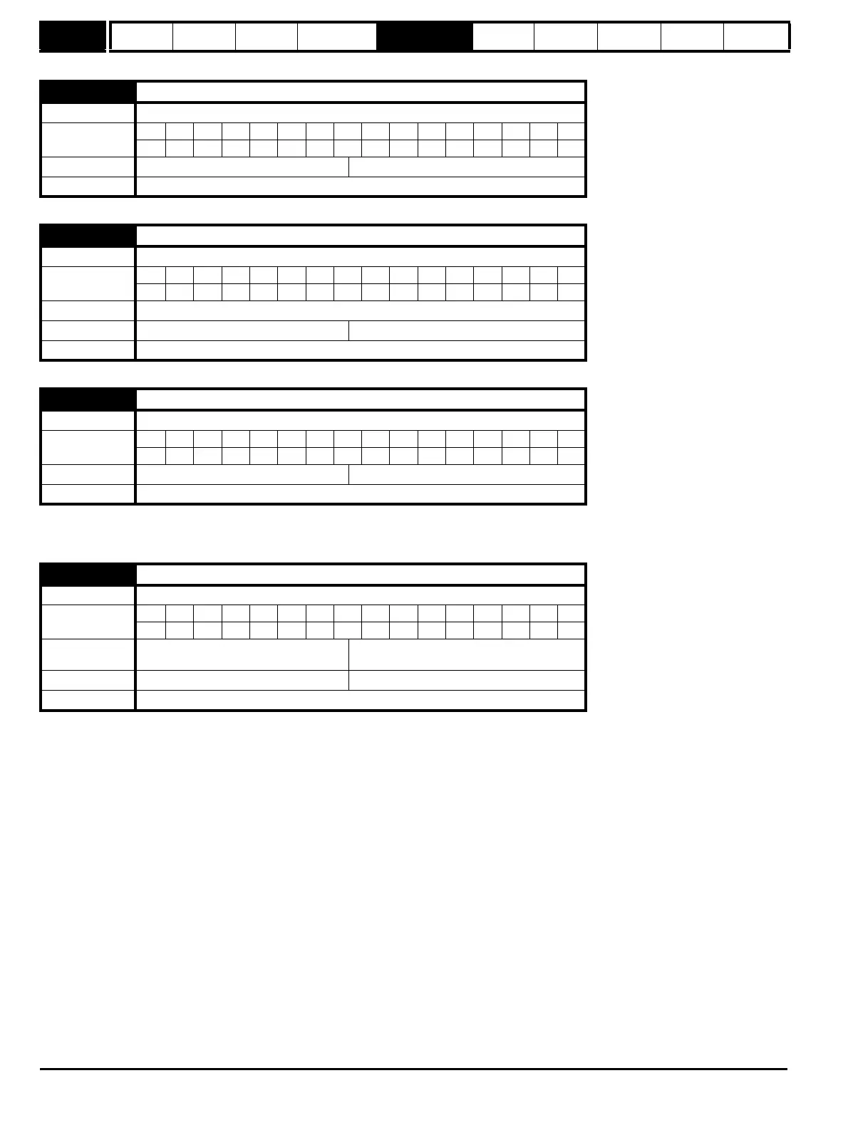
2.01 Post ramp reference
Drive modes Open-loop, Closed-loop vector, Servo
Coding
Bit SP FI DE Txt VM DP ND RA NC NV PT US RW BU PS
11111
Range Open-loop, Closed-loop vector, Servo ±SPEED_FREQ_MAX Hz/rpm
Update rate 4ms write
2.02 Ramp enable
Drive modes Closed-loop vector, Servo
Coding
Bit SP FI DE Txt VM DP ND RA NC NV PT US RW BU PS
1111
Coding RW, Bit, US
Default Closed-loop vector and Servo 1
Update rate 4ms read
2.03 Ramp hold
Drive modes Open-loop, Closed-loop vector, Servo
Coding
Bit SP FI DE Txt VM DP ND RA NC NV PT US RW BU PS
111
Default Open-loop, Closed-loop vector, Servo 0
Update rate 4ms read
2.04 Ramp mode select
Drive modes Open-loop, Closed-loop vector, Servo
Coding
Bit SP FI DE Txt VM DP ND RA NC NV PT US RW BU PS
1111
Range
Open-loop
Closed-loop vector, Servo
0 to 2
0 to 1
Default Open-loop, Closed-loop vector, Servo 1
Update rate 4ms read

 Loading...


