Parameter
structure
Keypad and
display
Parameter
x.00
Parameter
description format
Advanced parameter
descriptions
Macros
Serial comms
protocol
Electronic
nameplate
Performance RFC mode
Unidrive SP Advanced User Guide 407
Issue Number: 10 www.controltechniques.com
* Bit 14 is set to allow 32bit access
Writes when actual parameter type is different from
selected
The slave will allow writing a 32 bit value to a 16 bit parameter as long as
the 32 bit value is within the normal range of the 16 bit parameter.
The slave will allow a 16 bit write to a 32 bit parameter. The slave will
sign extend the written value, therefore the effective range of this type of
write will be -32768 to +32767.
Examples, if #1.28 has a range of ±100000, and #1.29 has a range of
±10000.
* Bit 14 is set to allow 32bit access
7.2.8 Exceptions
The slave will respond with an exception response if an error is detected
in the master request. If a message is corrupted and the frame is not
received or the CRC fails then the slave will not issue an exception. In
this case the master device will time out. If a write multiple (FC16 or
FC23) request exceeds the slave maximum buffer size then the slave
will discard the message. No exception will be transmitted in this case
and the master will time out.
Exception message format
The slave exception message has the following format.
Exception codes
The following exception codes are supported.
Parameter over range during block write FC16
The slave processes the write block in the order the data is received. If a
write fails due to an out of range value then the write block is terminated.
However, the slave does not raise an exception response, rather the
error condition is signalled to the master by the number of successful
writes field in the response.
Parameter over range during block read/write FC23
There will be no indication that there has been a value out of range
during a FC23 access.
7.2.9 CRC
The CRC is a 16bit cyclic redundancy check using the standard CRC-16
polynomial x16 + x15 + x2 + 1. The 16bit CRC is appended to the
message and transmitted LSB first.
The CRC is calculated on ALL the bytes in the frame.
7.2.10 Device compatibility parameters
All devices have the following compatibility parameters defined:
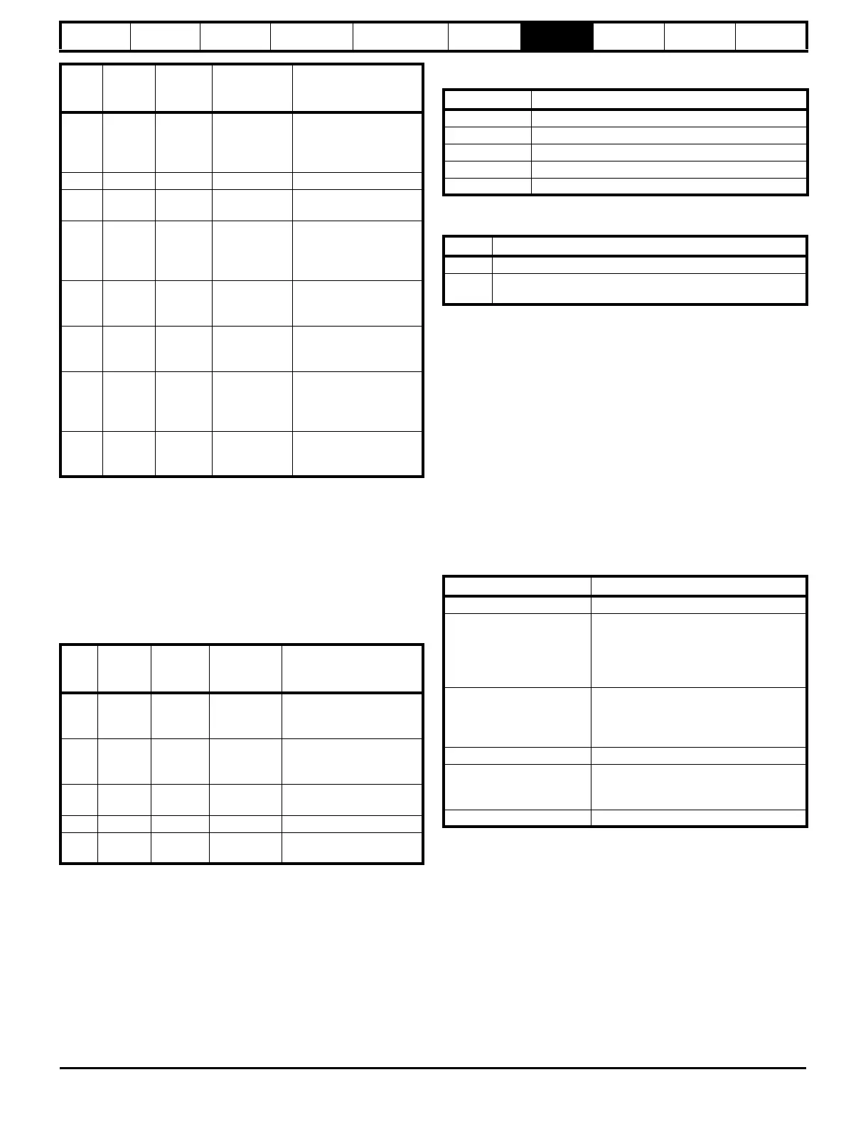
Read
Start
register
address
Number
of 16bit
registers
Response Comments
#1.28 127 1 0x5678
Standard 16 bit access
to a 32bit register will
return low 16bit word of
truncated data
#1.28 16511* 2 0x12345678 Full 32bit access
#1.28 16511* 1 Exception 2
Number of words must
be even for 32bit access
#1.29 128 1 0xABCD
Standard 16 bit access
to a 32bit register will
return low 16bit word of
data
#1.29 16512* 2 0xFFFFABCD
32bit access to a 16bit
register will return 32bit
sign extended data
#1.30 16513* 2 0x00000123
32bit access to a 16bit
register will return 32bit
sign extended data
#1.28
-
#1.29
127 2
0x5678,
0xABCD
Standard 16 bit access
to a 32bit register will
return low 16bit word of
truncated data
#1.28
-
#1.29
16511* 4
0x12345678,
0xFFFFABCD
Full 32bit access
Write
Start
register
address
Number
of 16bit
registers
Data Comments
#1.28 127 1 0x1234
Standard 16 bit write to a
32bit register. Value
written = 0x00001234
#1.28 127 1 0xABCD
Standard 16 bit write to a
32bit register. Value
written = 0xFFFFABCD
#1.28 16511 2 0x00001234
Value written =
0x00001234
#1.29 128 1 0x0123 Value written = 0x0123
#1.29 16512 2 0x00000123
Value written =
0x00000123
Byte Description
0 Slave source node address
1 Original function code with bit7 set
2 Exception code
3 CRC LSB
4 CRC MSB
Code Description
1 Function code not supported
2
Register address out of range, or request to read too many
registers
Parameter Description
Device ID Unique device identification code
Minimum slave response
time
The minimum delay between the end of a
message from the master and the time at
which the master is ready to receive a
response from the slave. Refer to para
11-26
Maximum slave response
time
When global addressing, the master
must wait for this time before issuing a
new message. In a network of devices,
the slowest time must be used
Maximum baud rate
32bit float data type
supported
If this data type is not supported then an
over range error will be raised if this data
type is used
Maximum buffer size Determines the maximum block size.

 Loading...


