Parameter
structure
Keypad and
display
Parameter
x.00
Parameter
description format
Advanced parameter
descriptions
Macros
Serial comms
protocol
Electronic
nameplate
Performance RFC mode
Menu 11
Unidrive SP Advanced User Guide 211
Issue Number: 10 www.controltechniques.com
When the data is transferred back to a drive, using 6yyy in Pr x.00, it is transferred to the drive RAM and then to the drive EEPROM. A parameter
save is not required to retain the data after power-down.
Onboard Application Lite user program data blocks
This type of data block is created when 5xxx in Pr x.00 is used to initiate the transfer. The Onboard Application Lite user program from a drive may be
transferred to/from internal flash memory from/to a SMART card. If the user program is transferred from a drive with no program loaded the block is
still created on the card, but contains no data. If this is then transferred to a drive the drive will then have no user program.
When transferring data between drives the following should be noted:
Parameter transfer failure
When parameter or default difference data is transferred to the drive the parameters are automatically saved to drive EEPROM. If the transfer from
the card fails for any reason the drive produces the appropriate trip. If the failure occurs after the transfer has begun, it is possible that some, but not
all the parameters will have been updated with the card data. However, if the transfer fails the parameters are not saved to drive EEPROM, therefore
only the RAM values will be incorrect. If the drive is powered down and then powered up again the original drive parameters will be restored.
Read-only function
Data blocks with numbers from 1 to 499 can be created or erased by the user. Data block with numbers 500 and above are read-only and cannot be
created or erased by the user. The whole card may also be protected from writing or erasing by setting the read-only flag. If the card or a data block
on the card is read-only, then the operation to erase the whole card is disabled.
Changing the drive mode
If the destination drive has a different drive mode to the parameters on the card, the drive mode will be changed by the action of transferring
parameters from the card to the drive. The only exception is that the mode cannot be changed to a mode that is not allowed for the particular
derivative of drive, e.g. Regen mode is not allowed with the Unidrive ES derivative. If an attempt is made to change to a disallowed mode the drive
produces a C.Typ trip.
Different voltage ratings
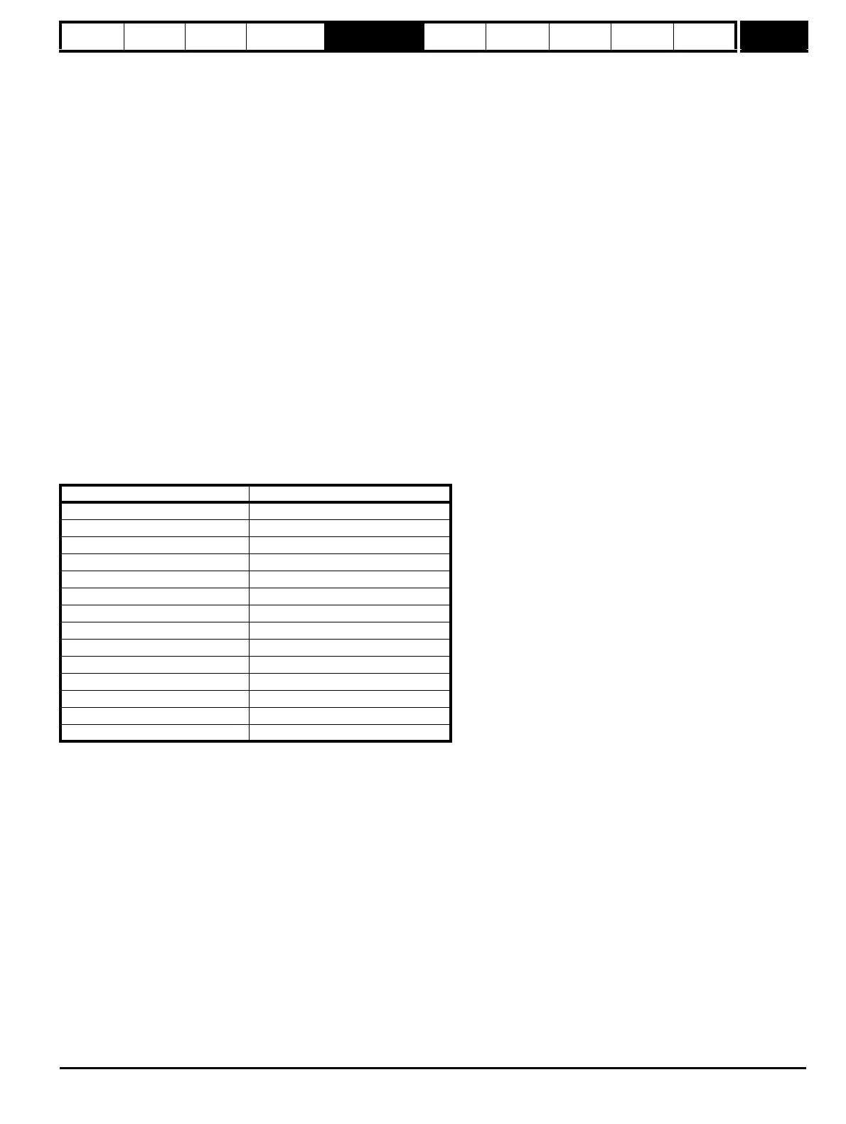
If the voltage rating of the source and destination drive are different then the parameters are transferred with the exception of rating dependent
parameters (RA attribute set, see table below), which are left at their default values. In this case a C.rtg trip is given as a warning that this has
happened. It is possible to suppress this warning trip for any data transfer to the drive, including a boot transfer at power-up by setting the warning
suppression flag for the whole card.
Different Solutions Modules installed
If the categories of the Solutions Modules installed to the source drive are different to the destination drive then the parameters are transferred with
the exception of the parameters in the menus of the modules that are different. These parameters are left at their default values. In this case a C.Optn
trip is given as a warning. It is possible to suppress this warning trip for any data transfer to the drive, including a boot transfer at power-up by setting
the warning suppression flag for the whole card.
Different current rating with a parameter file type data block
If the current ratings of the source and destination drive are different and the parameters stored as a parameter file (not differences from default) then
rating dependant parameters are set to their defaults and a C.rtg trip is produced as described above where the voltage ratings are different. It is
possible to suppress this warning trip for any data transfer to the drive, including a boot transfer at power-up by setting the warning suppression flag
for the whole card.
Different current rating with difference from defaults type data block
If the current ratings of the source and destination drives are different, but the parameters are stored as a difference from defaults file, the rating
dependant parameters are transferred from the card to the drive and the appropriate maximums are applied. The C.rtg is still produced unless it is
suppressed. To ensure that the performance of the destination drive is similar to that of the source drive, the speed controller gains and current
controller gains are scaled as shown in the table below. Note that the gain scaling is only applied when the data block number
is less than 500.
Parameter number Function
Pr 2.08 Standard ramp voltage
Pr 3.05 Regen unit voltage setpoint
Pr 4.05 - Pr 4.07, Pr 21.27- Pr 21.29 Current limits
Pr 4.24 User current maximum scaling
Pr 5.07, Pr 21.07 Motor rated current
Pr 5.09, Pr 21.09 Motor rated voltage
Pr 5.10, Pr 21.10 Rated power factor
Pr 5.17, Pr 21.12 Stator resistance
Pr 5.18 Switching frequency
Pr 5.23, Pr 21.13 Voltage offset
Pr 5.24, Pr 21.14 Transient inductance
Pr 5.25, Pr 21.24 Stator inductance
Pr 6.06 D.C. injection braking current
Pr 6.48 Mains loss ride through detection level

 Loading...


