Menus 15 to 17
SM-I/O Lt Tmr
Parameter
structure
Keypad and
display
Parameter
x.00
Parameter
description format
Advanced parameter
descriptions
Macros
Serial comms
protocol
Electronic
nameplate
Performance RFC mode
302 Unidrive SP Advanced User Guide
www.controltechniques.com Issue Number: 10
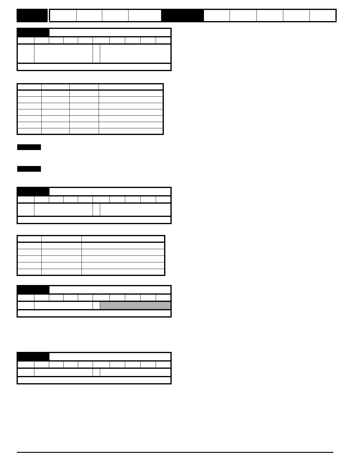
Terminal T2 is a voltage/current reference input. The setting of this parameter configures the terminal to the required mode.
In modes 2 and 3, a current loop loss trip will be generated if the current input falls below 3mA, and Pr x.50 will be set to a 2.
If 4-20 or 20-4 modes are selected and the drive trips on current loop loss (cL), analog reference 2 cannot be selected if the current reference is
<3mA. If 4-.20 or 20-.4 modes are selected, Pr x.03 will switch from a OFF to On to indicate that the current reference is <3mA.
If bi-polar operation is required, the -10V reference must be generated and supplied by an external power supply.
Terminal T3 is a voltage/current output. The setting of this parameter configures the terminal for the required mode.
This parameter displays the level of the analog signal present at analog input 1.
In voltage mode, this is a bipolar voltage input where the input range is ±10V.
In current mode, this is a unipolar current input having a maximum measurable input of 20mA. The drive can be programmed to convert the measured
current to any one of the defined ranges in Pr x.38. The selected range is converted to 0.0 - 100.0%.
This parameter is used to scale the analog input if so desired. However in most cases it is not necessary as each input is automatically scaled such
that for 100.0%, the destination parameters (defined by the settings of Pr x.43) will be at maximum.
x.38 Analog input 1 mode (Terminal T2)
RW Txt US
Ú
0-20(0), 20-0(1), 4-20(2),
20-4(3), 4-.20(4), 20-.4(5),
VoLt(6)
Ö
0-20(0)
Update rate: Background read
Value SK Display SP Display Function
0 0-20 0-20 0 to 20mA
1 20-0 20-0 20 to 0mA
2 4-20 4-20.tr 4 to 20mA with trip on loss
3 20-4 20-4.tr 20 to 4mA with trip on loss
4 4-.20 4-20 4 to 20mA with no trip on loss
5 20-.4 20-4 20 to 4mA with no trip on loss
6VoLtVOLt
±10V
x.39 Analog output 1 mode (Terminal T3)
RW Txt US
Ú
0-20(0), 20-0(1), 4-20(2),
20-4(3), VoLt(4)
Ö
0-20(0)
Update rate: Background read
Value Display Function
0 0-20 0 to 20mA
1 20-0 20 to 0mA
2 4-20 4 to 20mA
3 20-4 20 to 4mA
4 VoLt 0 to +10V
x.40 Analog input 1 level (Terminal T2)
RO Bi NC PT
Ú
±100 %
Ö
Update rate: Background write
x.41 Analog input 1 scaling (Terminal T2)
RW Uni US
Ú
0.000 to 0.400
Ö
1.000
Update rate: Background read

 Loading...


