Parameter
structure
Keypad and
display
Parameter
x.00
Parameter
description format
Advanced parameter
descriptions
Macros
Serial comms
protocol
Electronic
nameplate
Performance RFC mode
Menu 12
Unidrive SP Advanced User Guide 229
Issue Number: 10 www.controltechniques.com
Closed loop vector and Servo
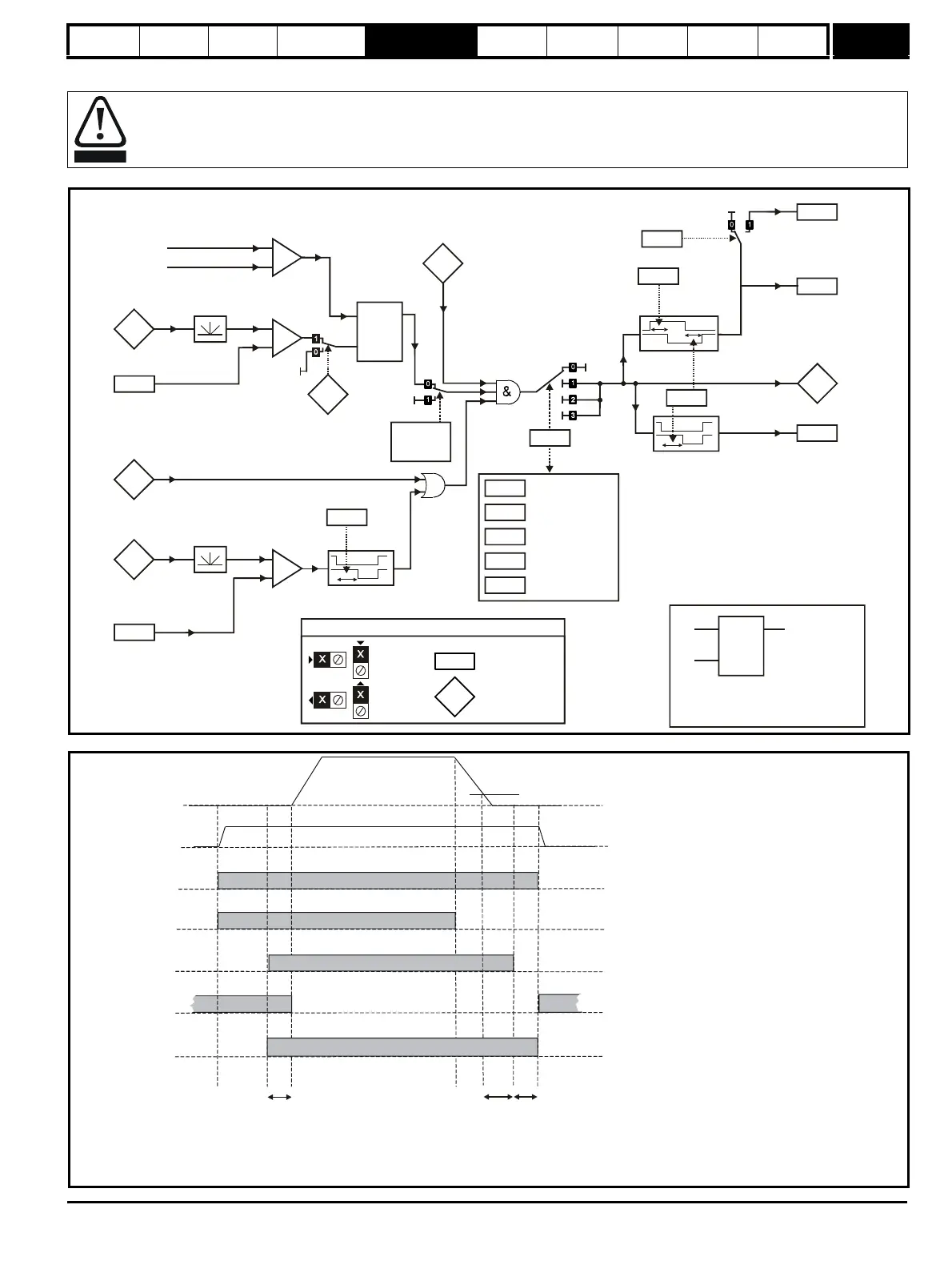
Figure 5-22 Closed-loop vector and Servo brake function
Figure 5-23 Closed-loop vector and Servo brake sequence
The brake control functions are provided to allow well co-ordinated operation of an external brake with the drive. While both hardware and
software are designed to high standards of quality and robustness, they are not intended for use as safety functions, i.e. where a fault or
failure would result in a risk of injury. In any application where the incorrect operation of the brake release mechanism could result in injury,
independent protection devices of proven integrity must also be incorporated.
4.01
Current
magnitude
Lower current
threshold
12.43
+
_
3.02
Speed
feedback
Brake apply
speed
12.45
+
_
Post-brake
release delay
(RW)
parameter
Read-only (RO)
parameter
Input
terminals
Output
terminals
If the reset input is 1, the output is 0.
If the reset input is 0, the output latches
+
_
Motor flux
7/8 x Rated flux
1.11
Reference
on
LAT
i
o
r
OR
Brake apply
speed delay
12.46
10.02
Drive active
Relay source
T25 digital I/O 2
output select
Position
control
mode
( = 1)
Closed-loop
vector = 0
Servo = 1
1
3.02
1. Wait for motor fluxed (closed-loop vector only)
2. Post-brake release delay
3. Wait for speed threshold
4. Wait for brake apply speed delay
5. Brake apply delay
Pr Brake apply speed
12.45
Pr
12.47
Pr
12.46
Pr
12.48
4.01
Pr Drive active
10.02
Pr Reference on
1.11
Pr Brake release
12.40
Pr Ramp hold
2.03
13.10
Pr Hold zero speed
6.08

 Loading...


