Parameter
structure
Keypad and
display
Parameter
x.00
Parameter
description format
Advanced parameter
descriptions
Macros
Serial comms
protocol
Electronic
nameplate
Performance RFC mode
Menus 15 to 17
SM-Uni Enc Pl
Unidrive SP Advanced User Guide 269
Issue Number: 10 www.controltechniques.com
Modes 4 to 7 are only available with the drive software versions 01.07.00 onwards and issue 4 SM-Universal Encoder Plus.
Each time the freeze input on the Solutions Module becomes active the non-marker position (Pr x.29 to Pr x.31) is stored in Pr x.35 to Pr x.37 and the
freeze flag (Pr x.39) is set. The freeze flag is not reset by the module and must be reset by the user. No other freeze conditions will be trapped if the
flag is set.
This parameter enables the Solutions Module to pass the freeze signal internally to the drive and other slots so that when a freeze occurs on the
Solutions Module the main drive position and/or other slots can also be frozen.
When Pr x.41 = 0 freeze occurs on the rising edge of the freeze input. When Pr x.41 = 1 freeze occurs on the falling edge of the freeze input.
In SINCOS mode (6) ONLY with no comms or commutation inputs, the internal differential Sin signal value is written to Pr x.42 as an unsigned
number.
A value greater then 32768 in Pr x.42 requires the user to minus 65536 to get the negative result. 0.675V approximate differential input produces
16384 (the maximum). The value given is quantized to 32 as the ADC produces a 10bit value with the outputs most significant bit in bit14 of the value
in Pr x.42.
0.5V gives approximately 12192 and 0.25V gives approximately 6112.
In AB.SErvo (3), FD.SErvo (4) or FR.SErvo (5) mode, the value in Pr x. 42 is obtained from the rules below. This permits the user to determine the
current segment and status of the commutation inputs (U high equals logic 1, U low equals logic 0):
Pr x.42 = 1000 * segment + 100 * U state + 10 * V state + W state
Example
If the commutation inputs equalled 110 (which is the 2nd segment) then Pr x.42 would be set to 2110.
Segment 9 means that the current commutation input is invalid.
All other modes follow the description for Pr x.44.
This parameter has no effect for SC.SErvo encoders.
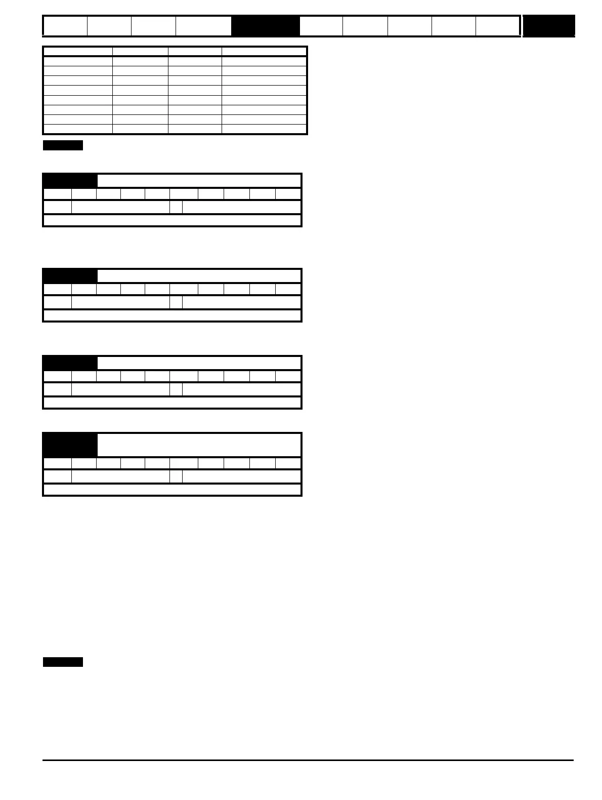
Value in Pr x.38 24V input 485 input Drive/slot bus input
0NoNo No
1 Yes No No
2NoYes No
3YesYes No
4NoNo Yes
5YesNo Yes
6NoYes Yes
7YesYes Yes
x.39 Freeze flag
RW Bit NC
Ú
OFF (0) or On (1)
Ö
OFF (0)
Update rate: 250μs write
x.40 Pass freeze to drive and other slots
RW Bit NC US
Ú
OFF (0) or On (1)
Ö
OFF (0)
Update rate: Background read
x.41 Freeze invert
RW Bit US
Ú
OFF (0) or On (1)
Ö
OFF (0)
Update rate: Background read
x.42
Encoder comms transmit register/Sin signal value/
commutation signal level
RW Uni NC
Ú
0 to 65535
Ö
0
Update rate: Background read

 Loading...


