Chapter 9 Page no. 1336
JC-DR-A-251.fm
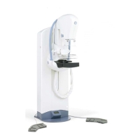
GE Healthcare Senographe DS
Revision 1 Service Information and Procedures Class A 2385072-16-8EN
Job Card D/R A251 - Paddle Holder Board
If you changed Paddle Holder Board 2359391 with 2369391-2, set DIP switch 4 to ON and DIP switches
1, 2, 3 to OFF. When the Paddle Holder is reassembled but before installing covers, install a standard
compression paddle.
1. Power on the Gantry and see if yellow LED DS2 next to the DIP switches is illuminated.
• If DS2 is NOT illuminated, the correct DIP switch setting has been found, and this procedure is
complete.
• If DS2 is illuminated, power off the Gantry and set DIP switch 2 to ON and DIP switches 1, 3, 4 to
OFF, then go step 2.
2. Power on the Gantry and see if DS2 is illuminated.
• If DS2 is NOT illuminated, the correct DIP switch setting has been found, and this procedure is
complete.
• If DS2 is still illuminated, power off Gantry and set DIP switch 1 to ON and DIP switches 2, 3, 4 to
OFF, then go step 3.
3. Power on the Gantry and see if DS2 is illuminated.
• If DS2 is NOT illuminated the correct DIP switch setting has been found, and this procedure is
complete.
• If DS2 is still illuminated the Force Sensor is probably faulty or possibly the newly installed Paddle
Holder Board is faulty.
TIP: use a 1.5 mm allen key or a similar small object to set the DIP switch positions.
Note:
When red LED DS3 next to the connector J1 is illuminated it indicates that Force Sensor is wire
disconnected or that the Force Sensor needs changing.
4. Once the Paddle Holder Board DIP switches are set as required, reinstall the Paddle Holder cover
(refer to Job Card PHY A044 - Remove/Reinstall Gantry Covers on page 523).
7 COMPLETION
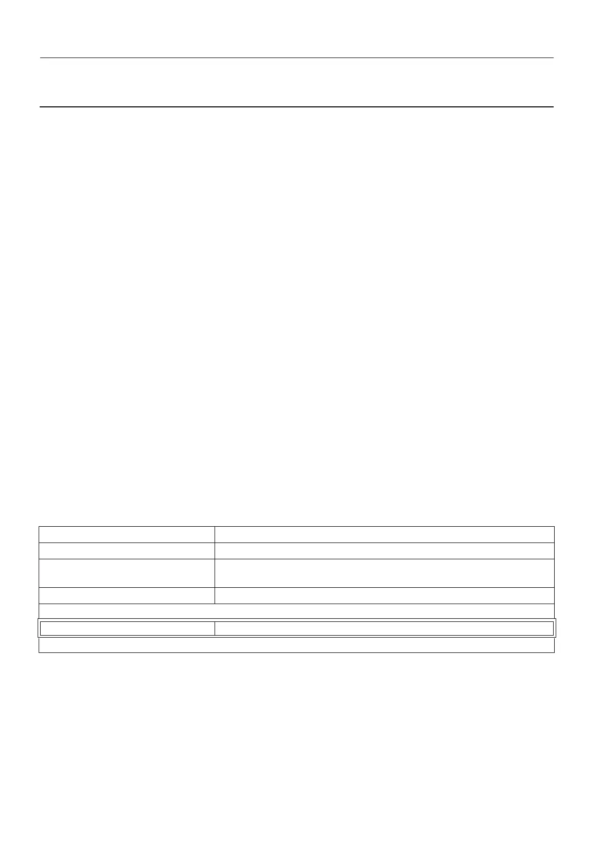
Carry out the following calibration procedures:
Calibrations - Checks Job Card
Gantry
Compression Force Sensor Job Card CAL A048 - Calibration of Compression Force Sensor on page
1709
Compression Thickness Job Card CAL A050 - Compression Thickness Calibration on page 1721
If Compression Thickness not OK, repeat calibrations from Compression Force Sensor
AOP/SNR Check Job Card ELE A038 - AOP Mode and SNR Check on page 707
If AOP/SNR Test not OK, repeat all calibrations
 Loading...


