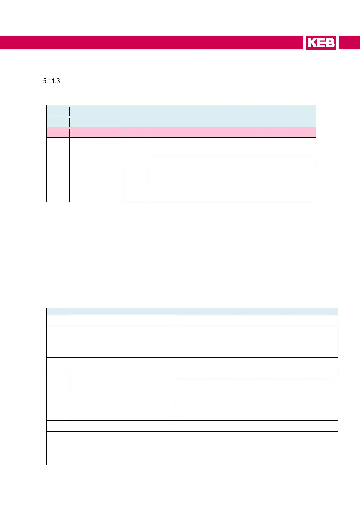
Power unit identification
The power unit is identified with de27 inverter data ID. The value is displayed deci-
mal, separated by dots.
Identification number of the various power units within a de-
vice size class
Version number of the power unit data
Identification for inverter rated power
(=> Operating instructions with technical data)
Example: the first released version of an 11F6 kW F6 inverter in housing size 2
with power unit code 53 would display the following value:
de27 = 15.2.1.53
If the "saved" value is different to the actual value, the control card has been set to
a power unit with different ID.
This causes the inverter changes to error 64 "ERROR power unit type changed".
By writing on parameter de27, the actual "inverter data ID" is adopted as "saved
inverter data ID" and the error can be reset.
The following data can be read by way that the most important inverter identifica-
tion data are also available if no manual is currently available:
Inverter rated current [in 0.01A]
Inverter software current limit [in 0.01A] for closed-loop
operation (depending on the inverter type and the setting
of is35 set current limit). The limit for the control can be
decreased by other parameters (dr12, is11)
Inverter rated voltage [in 0.1V]
inverter maximum DC voltage
Tripping threshold overvoltage error [in 0.1V]
inverter minimum DC voltage
Tripping threshold undervoltage error [in 0.1V]
inverter rated switching frequency
Rated switching frequency [in 0.01 kHz]
inverter maximum switching
frequency
Maximum available switching frequency (at reduced cur-
rent)
inverter intermed.circuit capacity [uF]
Capacity of the capacitors in the DC link
braking transistor default level
Value at which the braking transistor is activated voltage-
dependent in the default setting.
Value "zero" means that the device does not contain a
braking transistor.

 Loading...


