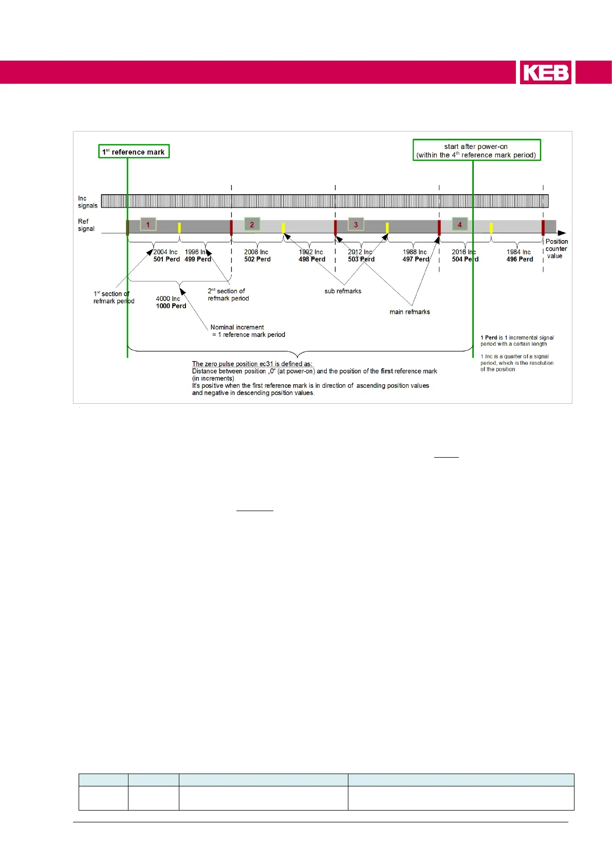
Figure 65: distance-coded reference marks
First there are the main reference marks, which have all the same distance to each
other, between them is always the same number of signal periods. This is the basic
distance (nominal increment) that must be entered in ec50.
Between the main reference marks are the sub reference marks (sub refmarks),
which all have a different distance to each other and also to the main reference
marks.
If at least two adjacent reference marks are passed (i.e. main and sub reference
mark), the absolute reference can be determined from the number of signal periods
between them, i.e. exactly where the drive is on the scale.
The distance between two reference marks is max. the base distance and min. half
of it. If the base distance is e.g. 1000 periods and one signal period is 20 µm long,
this is 20 mm.
Only when two reference marks have been passed, ec17 changes from 1 "encoder
identification running" to the recognized encoder type and the calculated position of
the zero signal is displayed in ec31.
The zero signal position in ec31 is also the absolute reference, which is defined
here as distance between the first reference mark (which is at the beginning of the
linear measuring system) and the position when the device is switched on.
If the 1st reference mark is in the direction of ascending position values from the
switch-on position, the zero signal position is positive. If it is in the direction of de-
scending position values, it is negative, which is usually the case.
Mode position calculation ec35 pos. calc. mode

 Loading...


