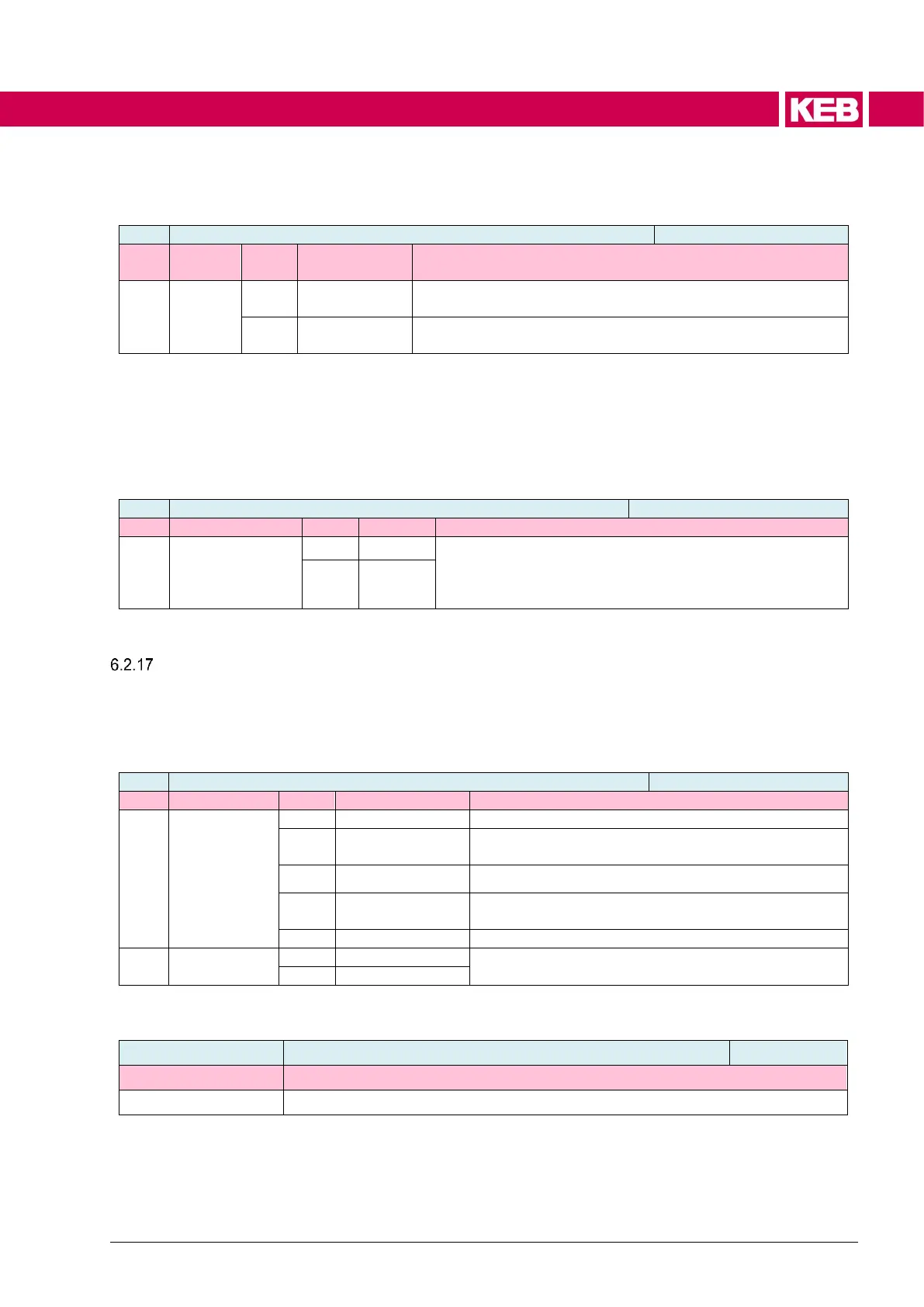
6.2.16.4 Motor model selection
Default setting, mandatory for operation at output frequen-
cies > 400 Hz.
Useful if Ld is very different from Lq. Therefore mandatory
for a reluctance machine.
*) Influence on the parameterization of the optimum current specification in the ta-
bles mo04, mo05
6.2.16.5 Consider deactivation of the dead time compensation in the motor model
consider dead-
time losses (only
for IGBT-model)
The voltage losses can be considered in the motor model
with deactivation of the dead time compensation depend-
ing on the speed (is03). This is only possible with the
IGBT model as dead time compensation type (is07, is24).
DC link voltage compensation
The current controller is pre-controlled by the DC link voltage compensation. The
output voltage can be limited to a max. value.
The influence of the DC link voltage compensation in open-loop operation is de-
scribed in the chapter 6.2.15.1 Voltage frequency operation.
No DC link voltage compensation
off, only curr, de-
coupling
No compensation for the current control, but for the
decoupling (=> 6.2.7.4 Decoupling)
Compensation and limitation of the maximum output
voltage
Activation of the PT1 filter
If the DC link voltage can oscillate due to the application, it can be smoothed by a
PT1 filter. Thus, a resonance can be avoided.
PT1 time for DC link voltage filtering
The DC link voltage compensation is activated with "Uic compensation mode“ = 2
or 3. That means, changes in the DC link voltage have no effect on the behavior of
the current control.
The maximum output voltage of the current controller is limited in mode 3 to the
value of is02.

 Loading...


