10.2 Diagnostic interface
The diagnostic interface is used to connect the F6 / S6 device with diagnostic tools, such
as COMBIVIS.
KEB DIN66019-II is used as protocol. This is an asynchronous serial protocol with the
following basic data:
1 start bit, 7 data bits, 1 parity bit (even), 1 stop bit.
These settings are fixed and can not be configured at the drive.
A description of the protocol is available from the KEB website.
➢ The diagnostics interface supports point-to-point connections via RS232 or
RS485 (full duplex). Networks via RS485 (half duplex) are not supported.
➢ The configuration of the diagnostic interface on the devices of control type P
differs from the configuration on the devices of control type A and K.
➢ The term "node address" or "node ID" often used in this chapter refers to the
identification number used by the DIN66019 protocol to address a KEB de-
vice.
➢ "Node address" or "Node ID" in this chapter does not mean the Node ID
which can be set via the rotary coding switches which is used to identify the
KEB device via the fieldbus interface (CAN or Ethernet).
➢ Information about the "Node ID" of the fieldbus interface can be found in the
Programming manual | Fieldbus systems, which can be downloaded from the
KEB website. Registration is required.
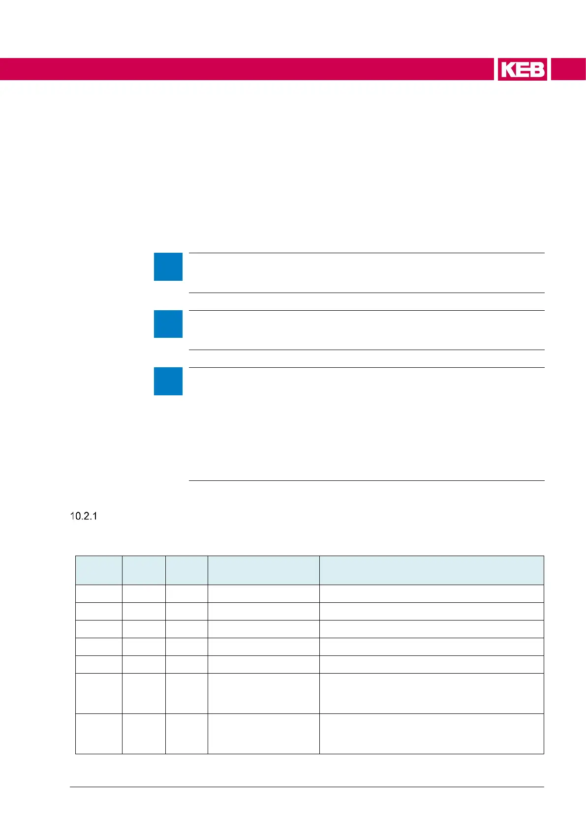
Configuration of the diagnostic interface on the devices of control type P
The diagnostic interface can be configured on the devices of control type P via the follow-
ing options.
Node address of the inverter object dictionary
Node address of the application object dictionary
Node address of the debugger object dictionary
Node address of the object dictionary to which
the communication of the fieldbus interface is
transmitted
Structure with configuration data for F6 / S6 op-
erators or for the application software and for the
connection to the file system

 Loading...


