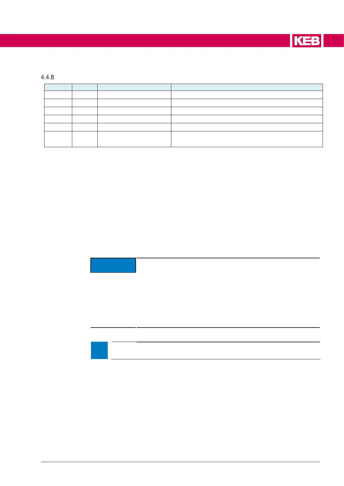
Maximum permissible motor current (in % dr03)
Inverter maximum current (only software limiting)
Maximum permissible inverter current (in % de28)
Software current limit in % turn-off current (OC current)
of the device. Resolution 0.01%
The maximum apparent current (not for v/f operation) can be preset via parameters
is35 set current limit, dr12 max. current % and is11 max. current [de28%].
de28 inverter rated current and de29 inverter maximum current are only display pa-
rameters and they display the inverter rated current and the maximum current of
the inverter. Due to e.g. insufficient cooling, it may be necessary to limit the maxi-
mum inverter current additionally with is11 to prevent OH errors.
The maximum permissible motor current can be adjusted in dr12 max. current %.
The effective current limitation is the lower value of is11 and dr12.
The maximum current of the drive (de29) is always determined as fixed upper limit.
This value is determined by is35 set current limit.
The setting range is 50.00% to 95.00% of the hardware-related turn-off current of
the inverter.
➢ The default value of the software current limit is 83.33% of the typi-
cal turn-off current to ensure safe operation. The displayed current
is always only an average value during a power module cycle. The
superimposed current ripple dependent on the motor, which is not
visible in the current display, can trigger the overcurrent cut-off, alt-
hough the display value of the current is clearly below the turn-off
current. The specified switch-off current threshold is a typical, toler-
ance affected value. If the software current limit is higher than the
default value, the design must be checked to prevent sporadic
overcurrent cut-offs.
➢ Parameter is35 is a Power-On Parameter. i.e. a change of the value is only
effective after restart.
Limitations can be considered separately by the inverter or the motor with dr12 and
is11.

 Loading...


