Error detector setups Error detector overview
Press Learn (if visible)
Press Run
The Sync operations gets the oscilloscope synchronized to the signal, the Learn operation acquires the
signal pattern into oscilloscope memory, and the Run operation starts the Error Detector testing for errors.
Note that the Learn operation only applies to some Bit error tests. Remember, Frame, Symbol, and
Character error tests do not require a Learn operation.
Then the typical sequence is to connect the DUT between the oscilloscope and the signal generator or
AWG for actual testing. After recabling, only a reSync and Run are needed, even for Bit testing, because
the signal
test pattern has already been acquired into the oscilloscope memory.
There are several cable arrangements you can use with the Serial Error Detector. T he first cable setup
specifica
lly applies to SATA, PCIe, and generic 8b10b bit testing, when a Learn operation is required
to acquire the signal test pattern into Error Detector memory. However, you can use this same cable
arrangement to verify Error Detector operation.
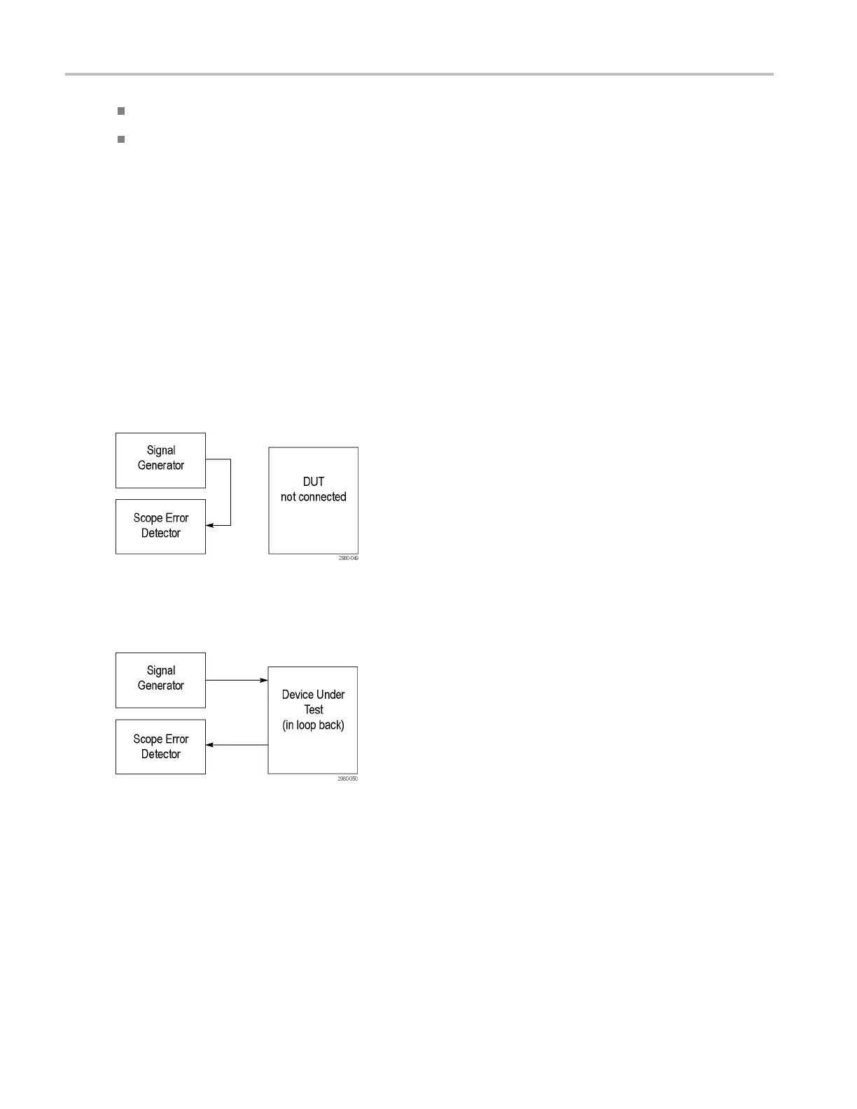
Connect the cabling as shown for the Learn operation in SATA, PCIe, and generic bit testing.
Having done the Learn operation, you can now insert the DUT in-between the Signal Generator and
the Error Detector as shown.
With the DUT inserted between the Signal Generator andtheSerialErrorDetector,allyouneedtodotoget
the Error Detector running is to press the Sync and Run buttons, because the L earn operation was completed
in the previous step. If you do another Learn operation, you risk learning errors created by the DUT.
To avoid having to rearrange the cables after the Learn operation, you may split the output of the signal
generator, putting one branch into the Error Detector and one branch into the DUT. Here the Learn
Operation is done on Ch1, but the actual error detection occurs on Ch2. You can adjust the amplitude
of the signal generator to account for the loss due to splitting the signal. This works because the Error
Detector learn operation stores the signal test pattern into error dete ctor memory, not channel memory.
206 DSA/DPO70000D, MSO/DPO/DSA70000C, DPO7000C, and MSO/DPO5000 Series
 Loading...


