Measurement setups Select an amplitude measurement
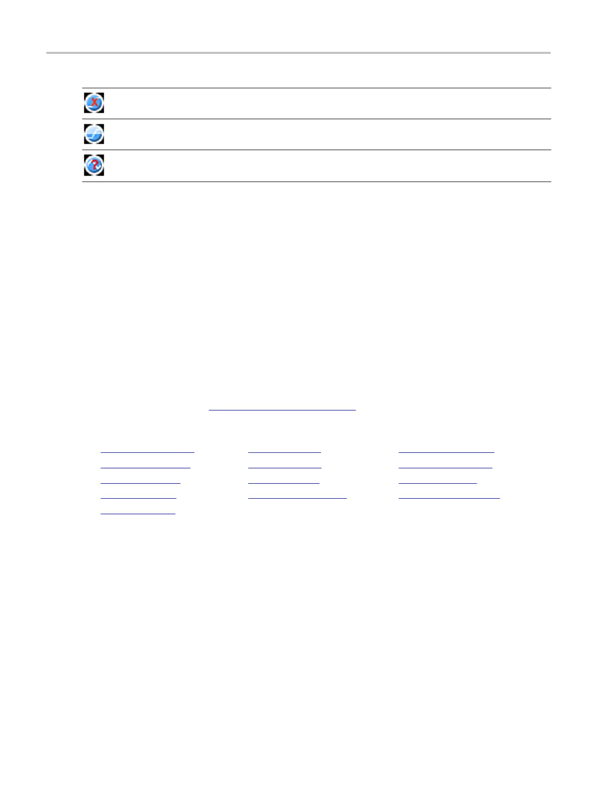
Icon Meaning example
The instrument cannot locate the s pecified edge of the signal.
The instrumen
t cannot measure a waveform that is “clipped” on the screen.
The instrument cannot locate the specified signal.
xxx
Null waveform data that is seen during measurements is usually seen when using ET mode, when the
instrument is still filling the waveform record. Warnings appear in the measurement readouts because of
ET mode, but eventually go away once the waveform record fills in. Filters can also cause null waveform
data, and measurements on the resulting math waveforms result in warnings.
Select an amplitude measurement
From the Measure menu, select Measurement Setup; then open the A mpl tab.
To use
Use the Ampl tab to select automatic amplitude measurements.
1. Select a source with the Channels Selector
(see page 258).
2. Click a Measurements button to add an Amplitude measurement to the Measure list:
Amplitude (see page 271) Low (see page 272) +Ovrshoot (see page 273)
AC RMS (see page 271) Max (see page 272) -Ovrshoot (see page 273)
Pk-Pk (see page 272) Min (see page 272) Mean (see page 273)
RMS (see page 272) Cycle RMS (see page 272) Cycle M ean (see page 273)
High (see page 272)
xxx
270 DSA/DPO70000D, MSO/DPO/DSA70000C, DPO7000C, and MSO/DPO5000 Series
 Loading...


