How to ? Trigger on setup/hold time violations
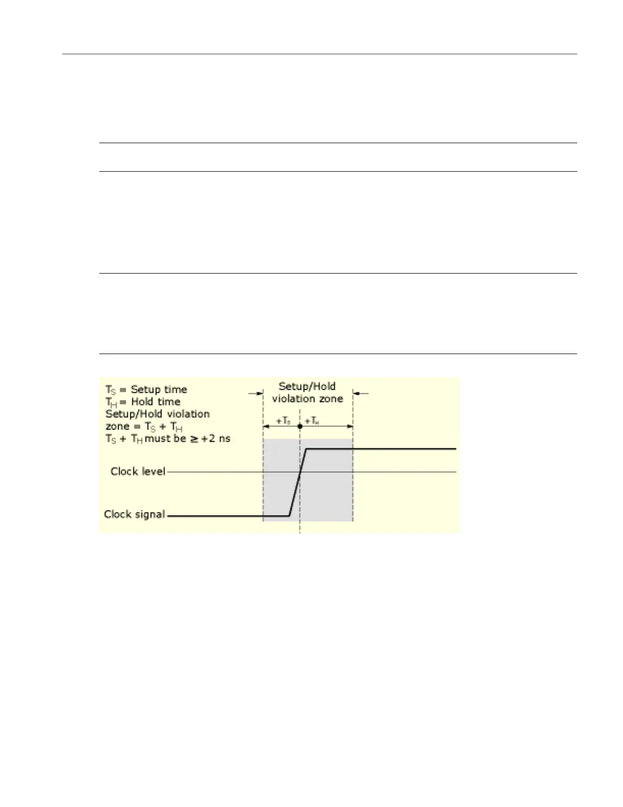
8. The instrument uses the clock level to determine when a clock edge occurs; the point that the clock
crosses the clock level is the reference point from which it measures setup and hold time settings.
To se t the cloc
k threshold level, click in the Clock Level entry box, and then use the multipurpose
knobs or pop-up keypad to enter a value.
NOTE. Both Clock and Data Levels can be set to a value appropriate to either the TTL or ECL logic
families by clicking TTL or ECL on the Data Level or Clock Level pop-up keypads.
9. To set the setup time relative to the clock, click in the Setup Time entry box, and then use the
multipurpose knob or pop-up keypad to enter a value.
10. To set the hold time relative to the clock, click in the Hold Time entry box, and then use the
multipurpose knob or pop-up keypad to enter a value.
NOTE. Positive setup time always leads the clock edge; positive hold time a lways follows the clock edge.
Setup time always leads the hold time by at least 2 ns (TS + TH ≥ 2 ns). Attempting to set either time to
reduce t
he 2 ns limit adjusts the other time to maintain the limit. In most cases, you will enter positive
values for both setup and hold time. Positive values set the instrument to trigger if the data source is still
settling inside the setup time before the clock or if it switches inside the hold time after the clock. You can
skew this setup/hold violation zone by entering negative values as shown below.
DSA/DPO70000D, MSO/DPO/DSA70000C, DPO7000C, and MSO/DPO5000 Series 653
 Loading...


