Installation and Maintenance Manual - Aastra 5000 AMT/PTD/PBX/0058/4/6/EN
Description des sous-ensembles 01/2011 Page 143
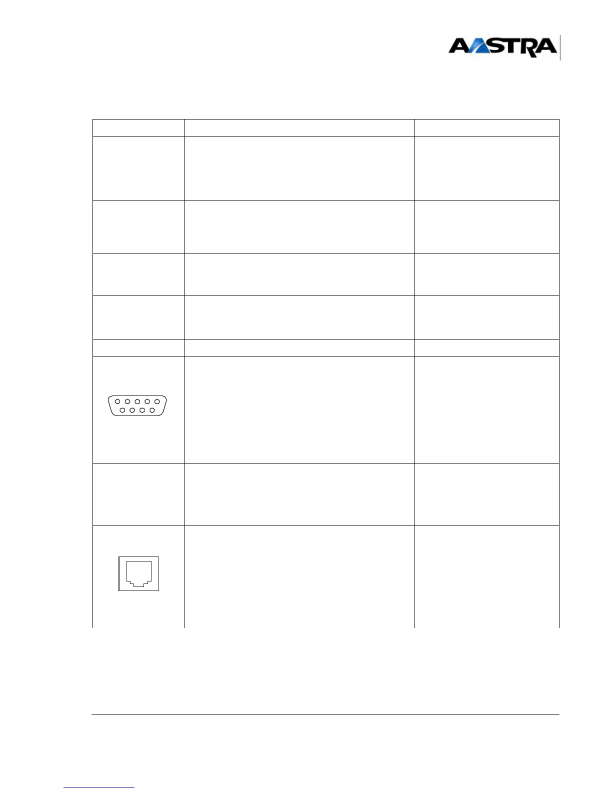
4.3.2 Physical description
NAME FUNCTIONS/CHARACTERISTICS CONTACTS
J1 (rear panel) Female connector, 192 pins:
• Backplane connection
• Includes the synchronous junctions (equipment
bus) used in the main cabinet, the reference clocks
and system bus.
J2 (rear panel) Female connector, 48 pins:
• Backplane connection
• Link with the connector of the
RUCV card in an
expansion cabinet.
J3 Female connector, 48 pins:
• Backplane connection
• Used for specific duplex
UCV signals.
J13 and J14 CMS 80-pin connectors: receive two optional daughter
cards - EIP No. 1 on J13 and EIP No.2 on J14 – to
increase the capacity of the VoIP function.
J10A and J10B HE14 connector
CONSOLE
(1)
Local access to operation in specific mode • Pin 1: DCD
• Pin 2: RXC
•Pin 3: TXC
• Pin 4: DTR
•Pin 5: GND
• Pin 6: DSR
•Pin 7: RTS
• Pin 8: CTS
• Pin 9: RI
USB (B)
(1)
USB connector in DEVICE mode • Pin 1: NC
• Pin 2: DNEG2
• Pin 3: DPOS2
• Pin 4: User ID
•Pin 5: GND
LAN
(1)
RJ45 8-pin connector: host the Ethernet 10/100BASE-
TX LAN access.
Note: Applications that use the
VTI/XML protocol (i2052 in
CTI, TWP mode) can be
connected directly to the
LAN port.
•Pin 1: TXP
•Pin 2: TXM
• Pin 3: RXP
•Pin 4: TLBR
•Pin 5: TLBR
• Pin 6: RXM
• Pin 7: RLBR
• Pin 8: RLBR
(1) Connector front view.
TABLEAU 4.5 DESCRIPTION OF UCV-D CARD CONNECTORS
 Loading...


