AMT/PTD/PBX/0058/4/6/EN Installation and Maintenance Manual - Aastra 5000
Page 252 01/2011 Description des sous-ensembles
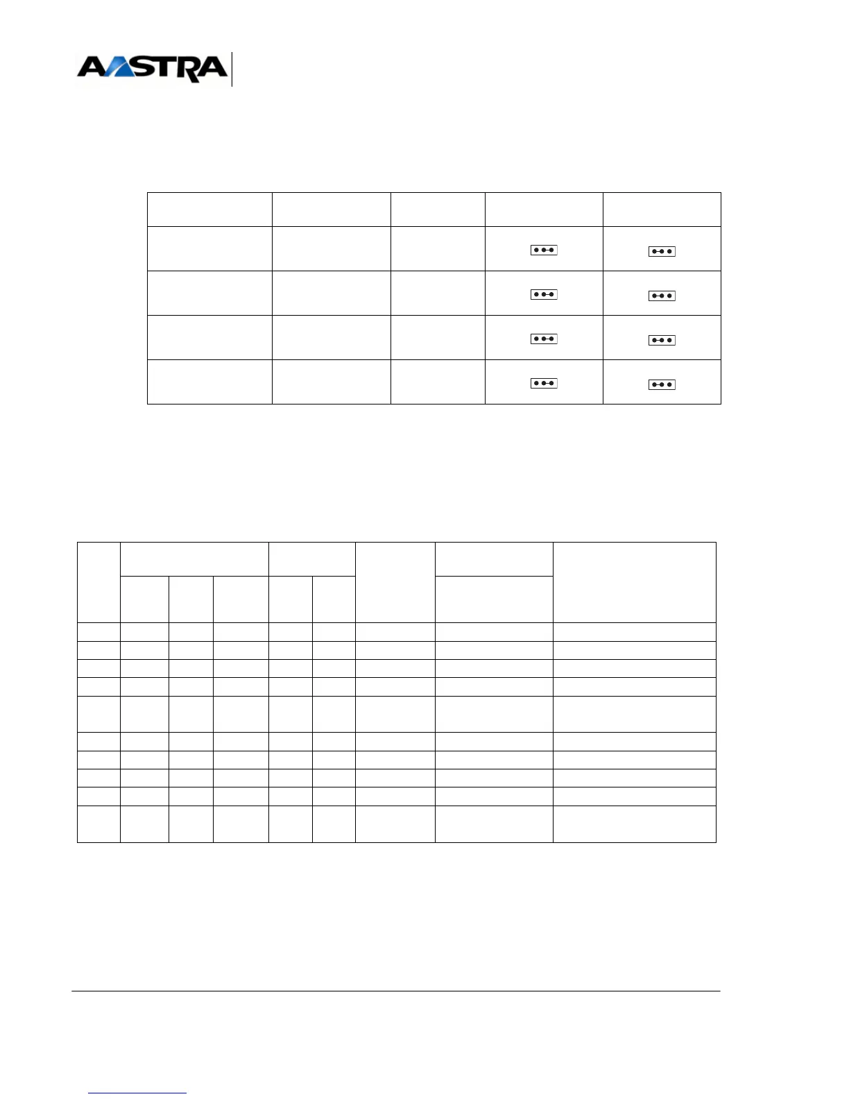
4.13.6.9 Hardware configuration
Switches SW1, SW2, SW3, and SW4 are used to set V10 or V28 mode.
TABLEAU 4.64 HARDWARE CONFIGURATION OF THE CA1 CARD
4.13.6.10Installation and wiring
The following tables give a list of the circuits in the V24 junction on the CA1 card. The
cable, with the reference HG4659, is used to wire the CA1 card interfaces.
Note: Circuit 107 “Data set ready” (PDP or DSR) is not present on the CA1 card. The
straps are not shown in this table.
TABLEAU 4.65 CONNECTING A DCE (CA1) TO A DTE (PC OR VT100 CONSOLE)
EQUIPMENT
NUMBER
CONNECTOR SWITCH V10 MODE V28 MODE
0J2SW1
1J3SW2
2J4SW3
3J5SW4
CIRC
T
DESIGNATION ETTD DIRECTION
CA1->DTE
CONNECTORS
CA1 CARD
FUNCTION
CCITT: EIA CA1 9-PIN
25-
PIN
TE0 to TE3:
104 RD RD NDE 2 3 ---> 1 Received data
103 ED ST/TD NDR 3 2 <--- 3 Transmitted data
108 TDP DTR DTR 4 20 <--- 8 card present output
106 PAE CTS CTS 8 5 ---> 7 flow control input
102 TS GND SGND 5 7 <--- 2 0 V return for junction
output
not wired
not wired
105 DPE RTS RTS 7 4 <--- 6 flow control output
109 DS CD CD 1-6 6-8 ---> 5 terminal present input
RET 5 7 4 0 V for junction input (with
V10)
 Loading...


