Installation and Maintenance Manual - Aastra 5000 AMT/PTD/PBX/0058/4/6/EN
Description des sous-ensembles 01/2011 Page 247
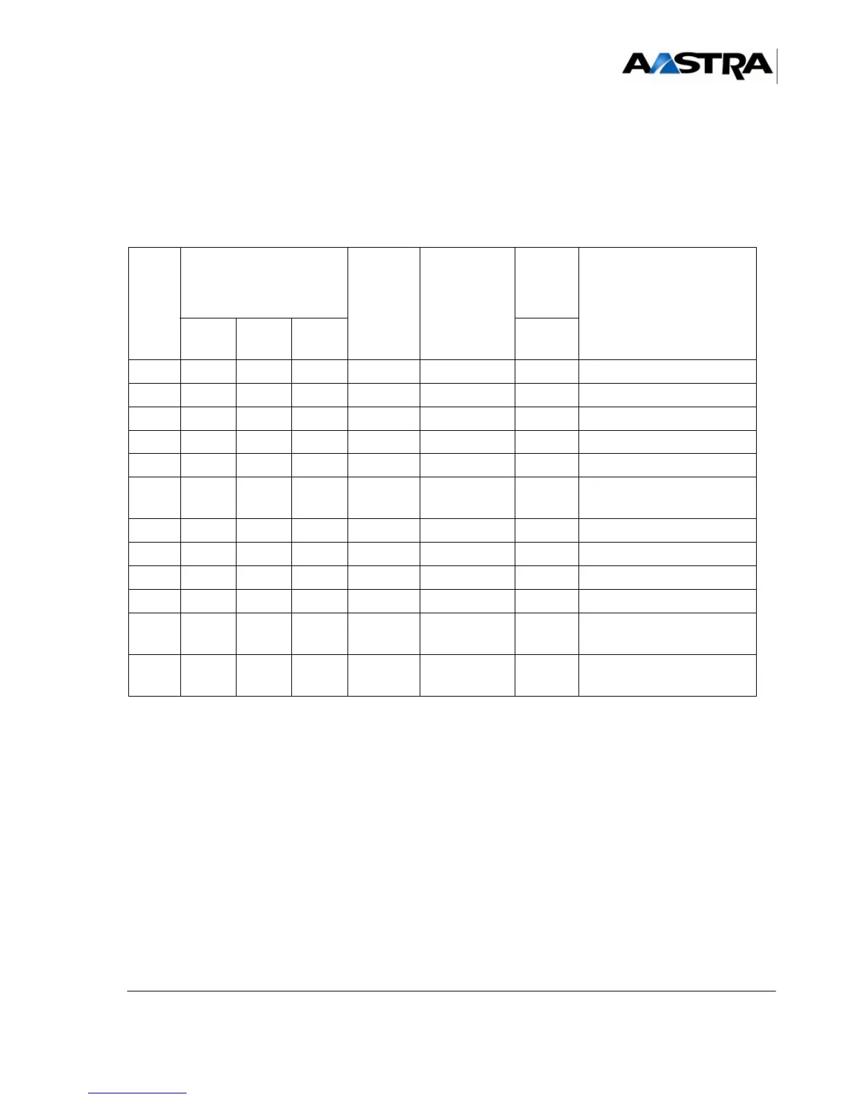
4.13.6.5 Installation and wiring
The shielded serial link cable with the reference HG4660 is used to wire interfaces on the
CS1 card. The following tables give a list of the circuits in the V24 junction on the CS1
card.
TABLEAU 4.59 CONNECTING A DCE (CS1) TO A DTE
CIRC
T
V24 SIGNAL NAME ETTD
ISO 2110
(25 PINS)
DIRECTION
CS1->DTE
CS1
CARD
CONNEC
TORS
FUNCTION
CCITT: EIA CS1*
Port1/
Port 2
104 RD RD NDE 3 <--- 2 Received data
103 ED ST/TD NDR 2 ---> 3 Transmitted data
108 TDP DTR DTR 20 <--- 8 card present output
106 PAE CTS CTS 5 ---> 20 flow control input
102 TS GND SGND 7 ---> 7 0 V return for junction output
115 HRM CR HR 15-17 ---> 17 clock received for received
data
113 XTC 24 ---> 24 clock signal sent
not wired
105 DPE RTS RTS 4 <--- 4 flow control output
109 DS CD CD 6-8 <--- 5 terminal present input
RET 7 0 V for junction input (with
V10)
114 HEM TC HT 15 ---> 15 clock received for data
transmitted
 Loading...


