AMT/PTD/PBX/0058/4/6/EN Installation and Maintenance Manual - Aastra 5000
Page 262 01/2011 Description des sous-ensembles
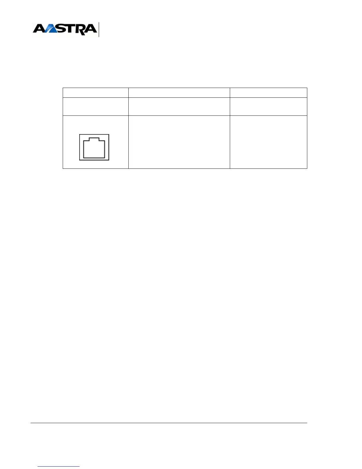
4.14.1.3 Physical description (see Figure 4.51 )
Connectors
TABLEAU 4.70 DESCRIPTION OF THE LA16X CARD CONNECTORS
Indicators
This card has no signalling indicator.
4.14.1.4 Hardware configuration
This card has no configuration microswitch.
4.14.1.5 Installation and wiring
The LA16X card can be hot-plugged in an AXD, AXL, AXS or AXS12 iPBX in normal
operation.
The requirements for connecting an analogue terminal are:
• the voltage and current measured across the station during conversation must be:
U > 12,4 V and I > 25 mA,
• line resistance (taking the set into account): 600 Ohms,
• all the analogue terminals connected to the PBX must be configured for Zref
impedance and self-regulation.
This card must be connected with cables with the following references: HG4765B,
HG4765C or HG4731.The minimum diameter of the cables has to be 26AWG (0.4mm).
NAME FUNCTION/CHARACTERISTIC CONTACTS
J1 96-pin connector:
backplane connection
L0 to L15 RJ45 connectors: each socket
provides one connection to an
analogue set
•Pin 4:
analogue set (i)+
•Pin 5:
analogue set (i)-
• Pins 1, 2, 3, 6, 7, and 8:
NC
 Loading...


