Installation and Maintenance Manual - Aastra 5000 AMT/PTD/PBX/0058/4/6/EN
Description des sous-ensembles 01/2011 Page 245
4.13.6.2 Physical description
4.13.6.3 Connectors
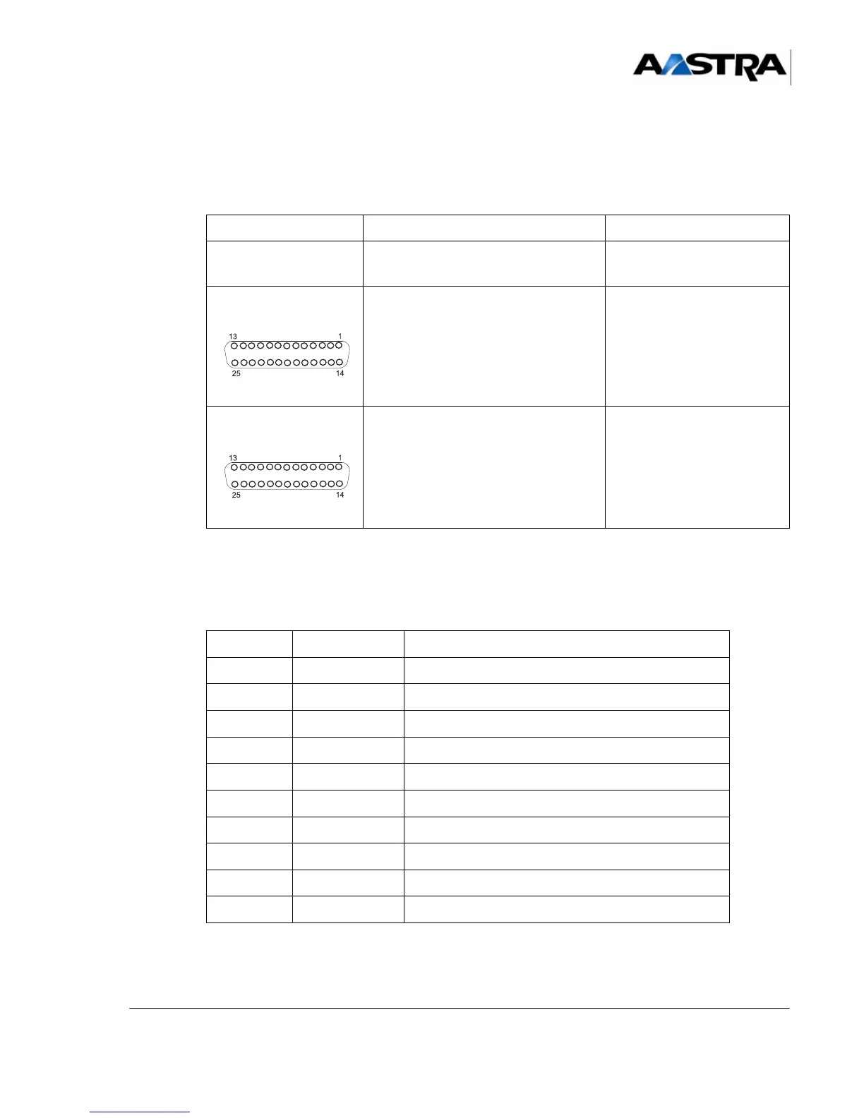
TABLEAU 4.55 DESCRIPTION OF CS1 CARD CONNECTORS
(1) SYNCHRONOUS connectors: the contacts on these connectors are described in
Tableau 4.56 .
TABLEAU 4.56 CONTACTS OF THE SYNCHRONOUS CONNECTORS ON THE CS1
CARD
NAME FUNCTION/CHARACTERISTIC CONTACTS
J1 96-pin connector: backplane
connection
SYNCHRONOUS
PORT 1
(front view)
Connecting equipment 0 (1)
SYNCHRONOUS
PORT 2
(front view)
Connecting equipment 1 (1)
PIN NO. CONTACT FUNCTION
2 TD Transmitted data
3 RD Received data
4 CTS Flow control input
5 DTR Data Terminal Ready output
7 GND 0 V return for junction output
8 CD Signal presence input
15 XTC Clock signal sent
17 TC Clock received for received data
20 RTS Flow control output
24 CR Clock received for received data
 Loading...


