Installation and Maintenance Manual - Aastra 5000 AMT/PTD/PBX/0058/4/6/EN
Description des sous-ensembles 01/2011 Page 293
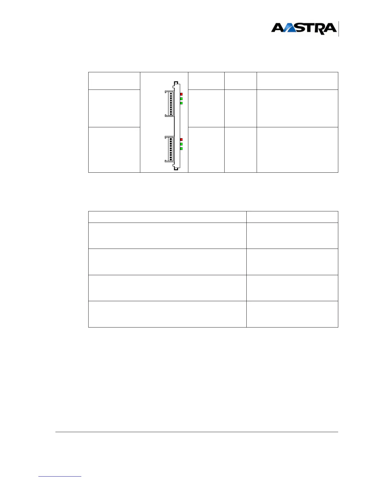
Indicators
TABLEAU 4.84 PRESENTATION OF THE LI1 CARD INDICATORS
4.14.14.4Hardware configuration
(1) Factory delivery configuration in bold characters.
(2) “x” is the microswitch number:
• CA1 microswitch associated with the link assigned to L1/RT1 connectors
• CA2 microswitch associated with the link assigned to L0/RT0 connectors
TABLEAU 4.85 CONFIGURING THE LI1 CARD
CONNECTOR
INDICATORS
NAME
Card
STATE EXPLANATION
L0/RT0
RX
TX
BUSY
Red
Green
Green
Status of the line:
• circuit busy
• circuit in transmit mode
• circuit in receive mode
L1/RT1
RX
TX
BUSY
Red
Green
Green
Status of the line:
• circuit busy
• circuit in transmit mode
• circuit in receive mode
DESIGNATION CONFIGURATION (1)(2)
Commissioning the line
•
TL operating
• TL disabled
CAx.1 on OFF
CAx.1 on ON (not used)
Type of gain:
•
Standard line (1.5 to 3.5 km)
• Short line (0 to 1.5 km)
CAx.2 on OFF
CAx.2 on ON
Signaling type:
•
E/M
•50 Hz
CAx.3 on OFF
CAx.3 on ON
Transmission to equipment over 2 or 4 wires:
•
2-wire
•4-wire
CAx.4 on OFF
CAx.4 on ON
 Loading...


