AMT/PTD/PBX/0058/4/6/EN Installation and Maintenance Manual - Aastra 5000
Page 292 01/2011 Description des sous-ensembles
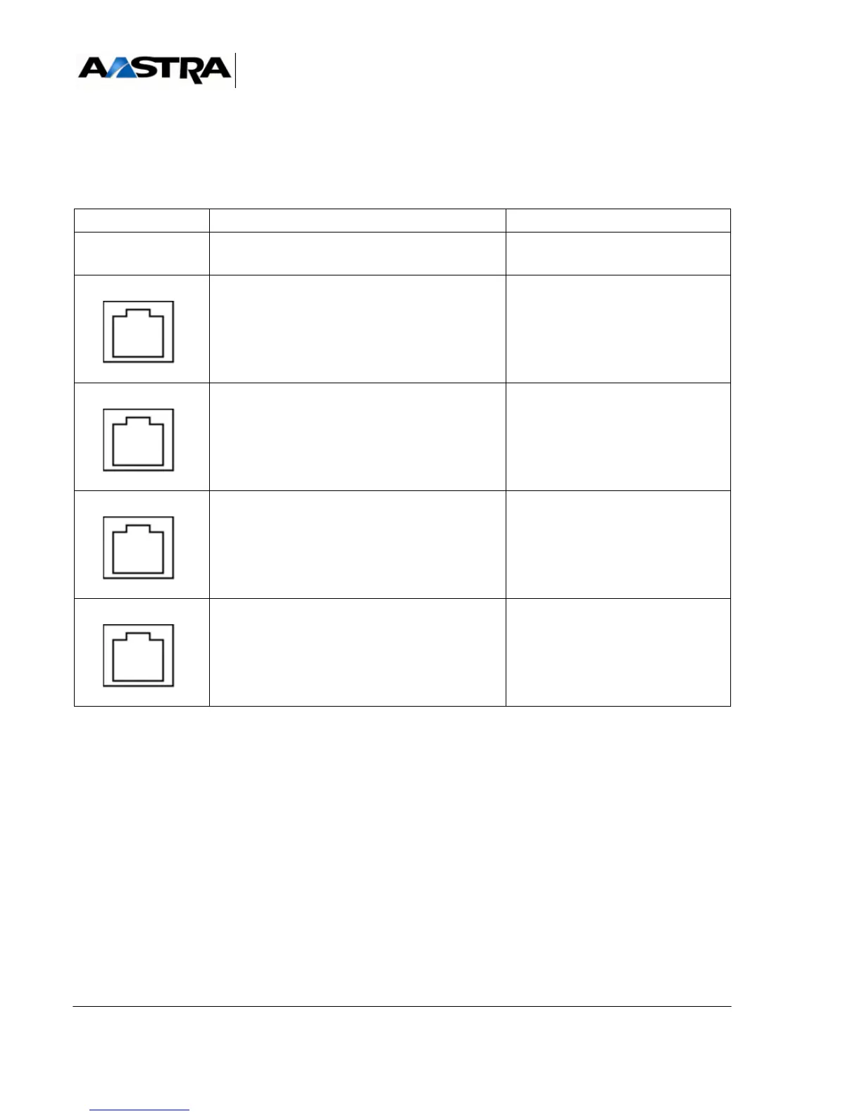
4.14.14.3Physical description (see Figure 4.63 )
Connectors
TABLEAU 4.83 DESCRIPTION OF LI1 CARD CONNECTORS
NAME FUNCTION/CHARACTERISTIC CONTACTS
J1 96-pin connector:
backplane connection
L0 RJ45 connector:
carries voice over an analog TL 0
•Pin 3: LRB0
•Pin 4: LRA0
•Pin 5: LERB0
•Pin 6: LERA0
L1 RJ45 connector:
carries voice over an analog TL 1
•Pin 3: LRB1
•Pin 4: LRA1
•Pin 5: LERB1
•Pin 6: LERA1
R/T0 RJ45 connector:
carries signaling over an analog TL 0
•Pin 2: T01
•Pin 3: R01
•Pin 4: R00
•Pin 5: TB00
• Pin 6: TA00
• Pin 7: GNDL
R/T1 RJ45 connector:
carries signaling over an analog TL 1
•Pin 2: T11
•Pin 3: R11
•Pin 4: R10
•Pin 5: TB10
• Pin 6: TA10
• Pin 7: GNDL
 Loading...


