AMT/PTD/PBX/0058/4/6/EN Installation and Maintenance Manual - Aastra 5000
Page 198 01/2011 Description des sous-ensembles
4.10.2 Physical description
The EXT1-S6 card is fitted on the front panel of RJ45 sockets for the equipment
interfaces
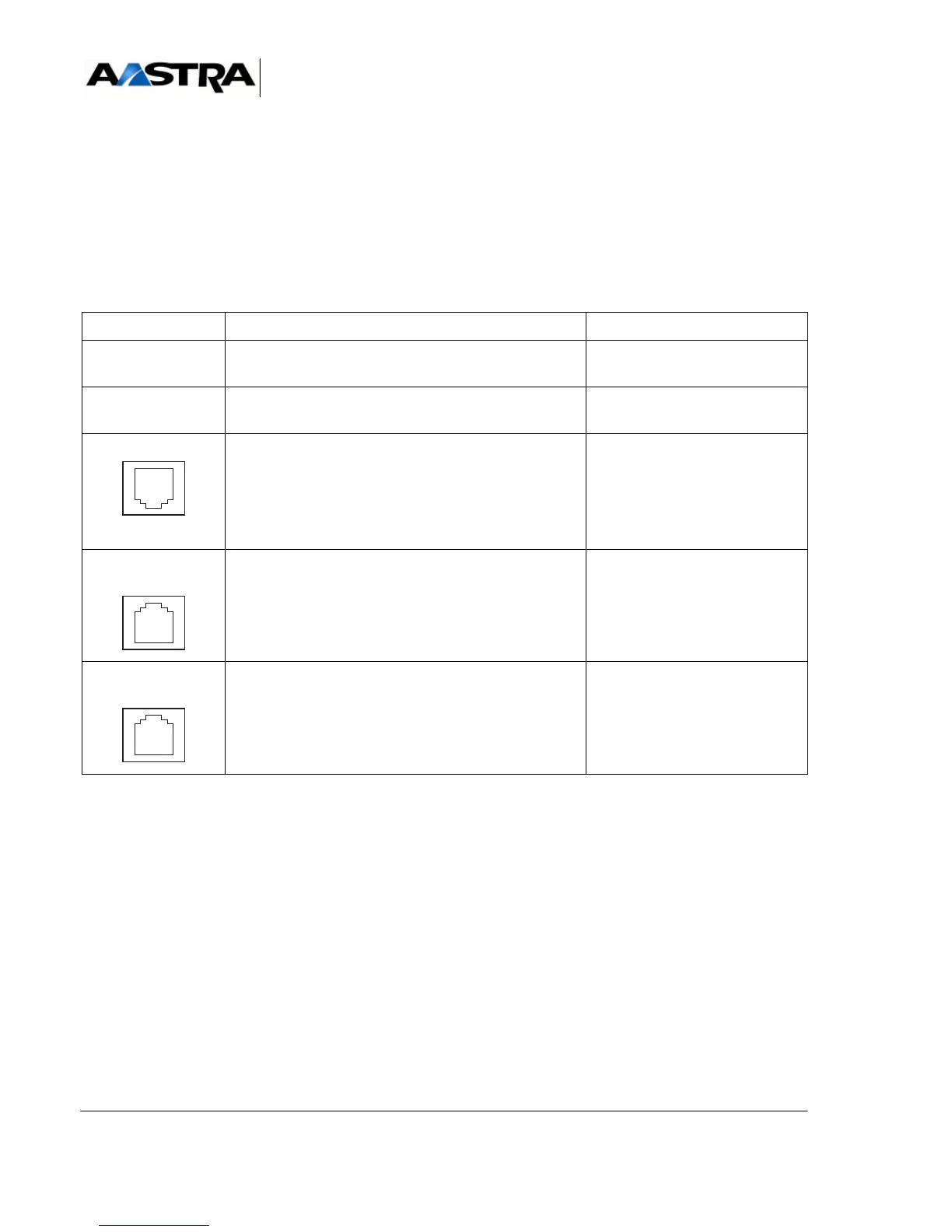
4.10.2.1 Connectors
(1) Connector front view.
(2) Tableau 4.16 and Figure 4.20 give the details relating to the command relays.
TABLEAU 4.27 DESCRIPTION OF EXT1-S6 CARD CONNECTORS
4.10.2.2 Indicators
The EXT1-S6 card does not have any indicators on the front panel.
NAME Function/characteristic contacts
J5 48-pin connector for LVDS link with the processor
card
J6 48-pin connector for power supply, and clock and
interruption signals.
S/T0, S/T1 (1) RJ45 connectors: T0/S0 access.
Note: Connecting S0 peripherals (S
sets or DECT base stations)
requires a twisted cable or
S0/T0 adaptor.
• Pins 1 and 2: NC
•Pin 3: EDX
• Pin 4: RDX
• Pin 5: NRDX
• Pin 6: NEDX
• Pins 7 and 8: NC
A0 to A3
(1)
RJ45 connectors: used to connect 4 analogue sets. • Pin 4: LAX+
• Pin 5: LAX-
• Pins 1, 2, 3, 6, 7, and 8: NC
N0 to N1
(1)
RJ45 connectors: used to connect 2 digital sets. • Pin 4: LNX+
•Pin 5: LNX-
• Pins 1, 2, 3, 6, 7, and 8: NC
 Loading...


