AMT/PTD/PBX/0058/4/6/EN Installation and Maintenance Manual - Aastra 5000
Page 152 01/2011 Description des sous-ensembles
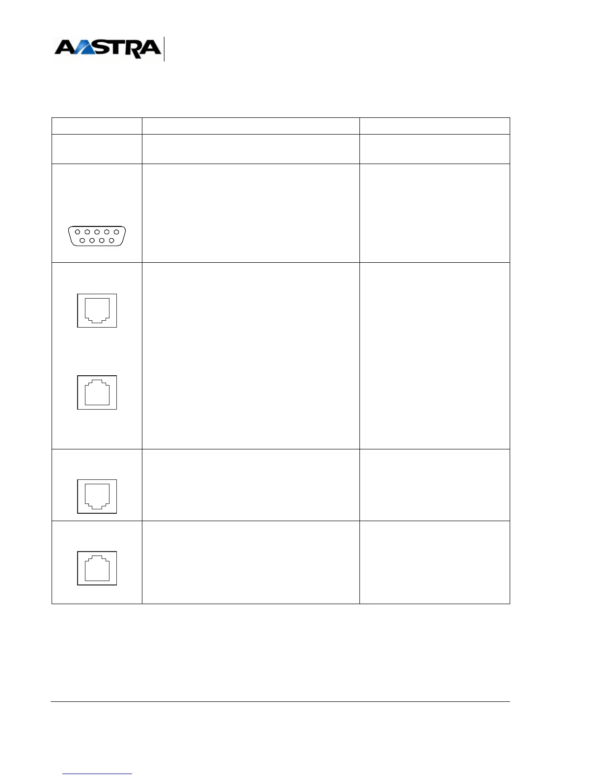
4.4.2.1 Connectors
NAME FUNCTIONS/CHARACTERISTICS CONTACTS
J1 (rear panel) Female connector, 192 pins:
link with the UCV-D card
CONSOLE
(1)
DB9-M connector: reserved for the manufacturer.
DECT P
(1)
DECT S
(1)
RJ45 double connector: primary and secondary
DECT synchronisation ports, for radio base stations
DECT P:
• Pin 1: AHGA
• Pin 2: AHGB
• Pin 3: PHBIT1
• Pin 4: PHDECT1
• Pin 5: NHDECT1
• Pin 6: NHBIT1
• Pin 7: HEXTA
• Pin 8: HEXTB
DECT S:
• Pin 1 and 2: L0V
• Pin 3: PHBIT2
• Pin 4: PHDECT2
• Pin 5: NHDECT2
• Pin 6: NHBIT2
•Pins7and8: L0V
PRINTER
(1)
Not used •
MUSIC
(1)
8-pin RJ45 connector: hosts an external source of
music-on-hold.
MUSA: Input impedance 15 Kohms.
MUSB: Input impedance 600 Kohms.
ETM: external source present.
• Pin 2: JP12
• Pin 3: GNDL
•Pin 4: MUSA
•Pin 5: ETM
• Pin 6: GNDL
•Pin 7: MUSB
• Pins 1 and 8: NC
(1) Connector front view.
TABLEAU 4.7 DESCRIPTION OF IUCV-D CARD CONNECTOTRS (1/2)
 Loading...


