AMT/PTD/PBX/0058/4/6/EN Installation and Maintenance Manual - Aastra 5000
Page 250 01/2011 Description des sous-ensembles
4.13.6.8 Physical description (see Figure 4.48 )
Connectors
TABLEAU 4.61 DESCRIPTION OF CA1 CARD CONNECTORS
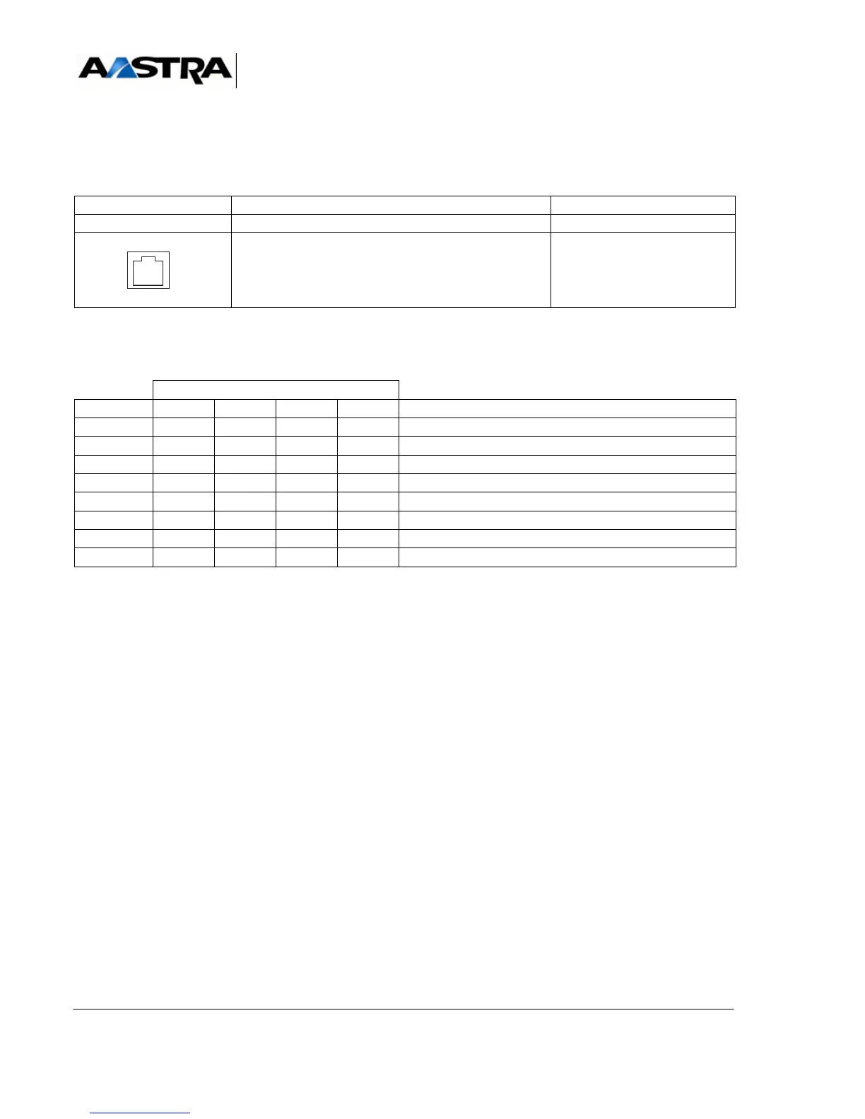
(1) Connectors TE0 to TE3: the contacts of these RJ45 connectors are described in
Tableau 4.62 .
TABLEAU 4.62 DESCRIPTION OF CA1 CARD CONNECTORS TE0 - TE3
NAME FUNCTION/CHARACTERISTIC CONTACTS
J1 96-pin connector: backplane connection (1)
TE0 to TE3:
Connecting equipment items 0 to 3
(2)
LINE NO.
PIN NO. * TE3 TE2 TE1 TE0 FUNCTION
1 TD3 TD2 TD1 TD0 Transmitted data
2 GND GND GND GND 0 V return for junction output
3 RD3 RD2 RD1 RD0 Received data
4 RET3 RET2 RET1 RET0 0V return for junction input (V10)
5 DTR3 DTR2 DTR1 DTR0 Data Terminal Ready output
6 CTS3 CTS2 CTS1 CTS0 Flow control input
7 RTS3 RTS2 RTS1 RTS0 Flow control output
8 CD3 CD2 CD1 CD0 Data terminal input
 Loading...


