AMT/PTD/PBX/0058/4/6/EN Installation and Maintenance Manual - Aastra 5000
Page 82 01/2011 Description et caractéristiques d’un PBX
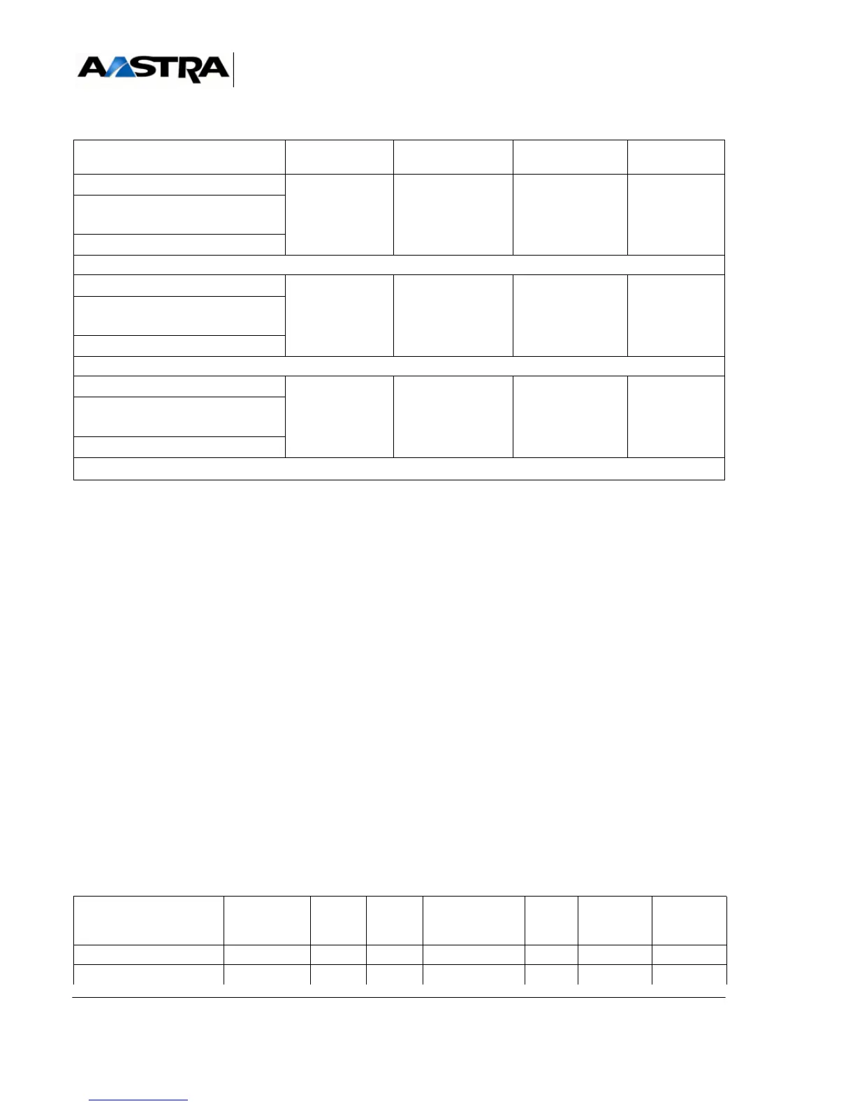
TABLEAU 3.2 LIST OF AXD IPBX SUBASSEMBLIES
(1) If this figure is reached: equipment cards cannot be installed. If the number of CLX cards is below 12: any equipment
card can be added.
(2) A - max number of LT2 = 6
B - max number of IPS = 1
C- max number of PT2 (32 V) = 4
D - max number of PT2 (32 V) + LT2 = 8
E- max number of DECT base stations = 40 (10 LD4N in X mode, with iPBX software release R4.1 – Other cases:
max number of base stations = 24)
F- max number of CLX (LD4N in X mode with iPBX software release 4.1 min, LT2, PT2, CP1, CS1, CA1, MUM) = 12
G- max number of CLX (case of LD4 or LD4N not in X mode, LT2, PT2, CP1, CS1, CA1, MUM) = 10
If case F is reached (CLX = 12), no other card is accepted in the main cabinet.
If case G is reached (CLX = 10), no other card is accepted in the main cabinet.
(3) The LD4, LD4N, LD4X and LT2 synchronising cards must be located in slots 0 to 5 of the AXD main cabinet when
they are to be used to provide the carrier (RTCP) reference clocks for the main card.
3.4.2 Aastra XS/XL
The subassemblies in each of the AXL, AXS, AXS12 and AXS6 iPBXs are presented in a
tree in 3.3.
Nota : The quantities indicated are the maximum hardware and software quantities for
each type of card. These quantities also depend on the configuration rules
(see Section3.5 ) and engineering rules of each site.
Simplex
12 12 12
Simplex with secure power
supply
Duplex
LI1
Simplex
12 12 12
Simplex with secure power
supply
Duplex
BTX
Simplex
11 11
Simplex with secure power
supply
Duplex
SUBASSEMBLIES AXL
Main Cabinet
A2XL A3XL AXS
Cabinet
Main
A2XS AXS12 main
cabinet
AXS6 main
cabinet
Power supply module 123 1 21 1
Battery (option) 123 1 21 1
Subassemblies MAIN CABINET
AXD
AXD EXPANSION
CABINET
A2XD A3XD
List of the sub-assemlies in AXD iPBXs - Folio 6 de 6 -
 Loading...


