Installation and Maintenance Manual - Aastra 5000 AMT/PTD/PBX/0058/4/6/EN
Description des sous-ensembles 01/2011 Page 157
4.5 RUCV-D card
4.5.1 Functional description
The RUCV-D card is installed instead of the UCV-D card in the expansion cabinets. Its
primary function is to distribute and monitor the status of the line equipment bus and PCM
synchronous trunks at the positions of the expansion cards.
It includes a command interface for 16 equipment cards and 8 PCM trunks.
4.5.2 Physical description
4.5.2.1 Connectors
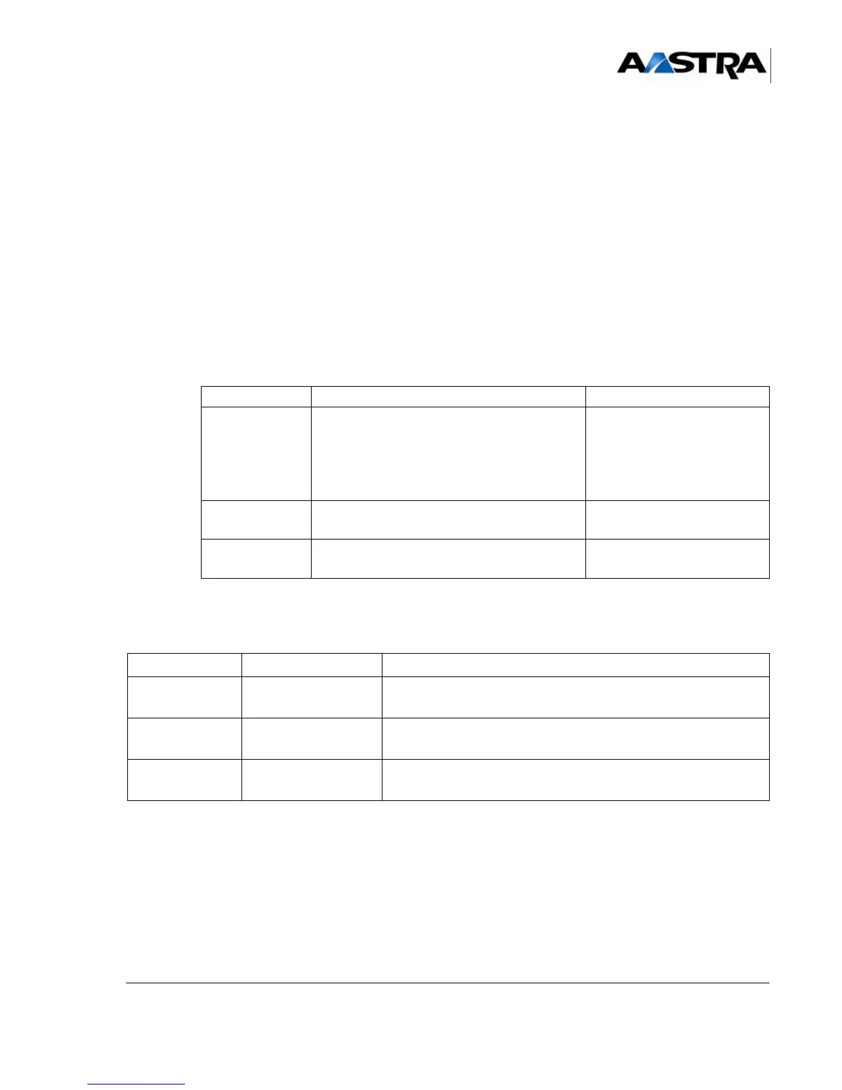
TABLEAU 4.11 DESCRIPTION OF RUCV-D CARD CONNECTORS
4.5.2.2 Indicators
NAME FUNCTION CONTACTS
J1 Female connector, 192 pins:
backplane connection.
It includes the synchronous junctions used in
the expansion cabinet, the reference clocks
and system bus
J2 (rear panel) Female connector, 48 pins:
connection to the main cabinet
J3 Connector with 8 pins (HE14): reserved for
the manufacturer.
INDICATOR STATE EXPLANATION
LINK (green)
Green flashing
ON green or OFF
Clock received from UCV-D
No clock (UCV stopped or cable disconnected)
ACCS (green)
Green flashing access to one of the expansion cards of the current cabinet
ACT (green) ON green
Off
Card active
Card not active
TABLEAU 4.12 OVERVIEW OF RUCV-D CARD INDICATORS
 Loading...


