Installation and Maintenance Manual - Aastra 5000 AMT/PTD/PBX/0058/4/6/EN
Description des sous-ensembles 01/2011 Page 265
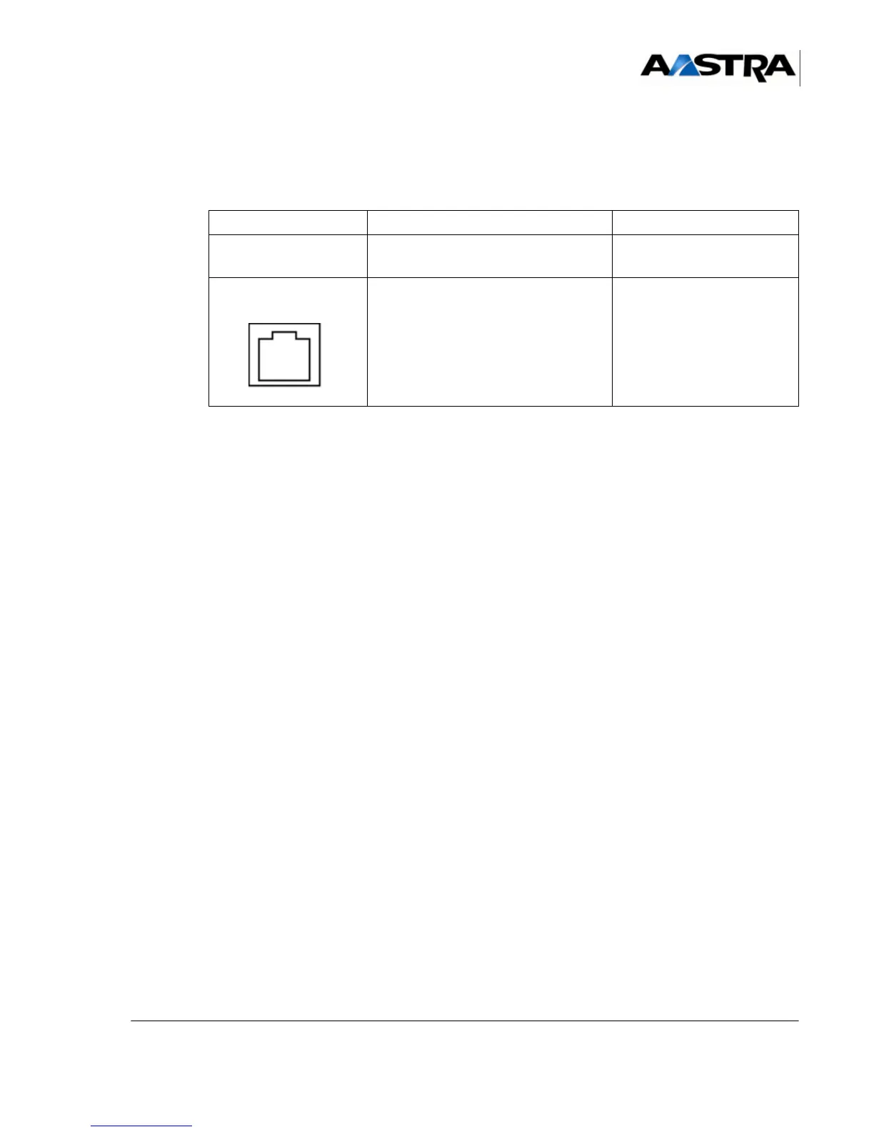
4.14.3 Physical description (see Figure 4.53 )
Connectors
TABLEAU 4.71 DESCRIPTION OF LA16X-8 CARD CONNECTORS
Indicators
This card has no signalling indicator.
4.14.3.1 Hardware configuration
This card has no configuration microswitch.
4.14.3.2 Installation and wiring
The LA16X-8 card can be hot-plugged in an AXD, AXL, AXS or AXS12 iPBX in normal
operation.
The other constraints relating to installing and wiring the LA16X card are identical to those
for the LA16X-8 card (see Section 4.14.1.5).
The minimum diameter of the cables has to be 26AWG (0.4mm).
NAME FUNCTION/CHARACTERISTIC CONTACTS
J1 96-pin connector:
backplane connection
L0 to L7 RJ45 connectors: each socket
provides one connection to an
analogue set
•Pin 4:
analogue set (i)+
•Pin 5:
analogue set (i)-
• Pins 1, 2, 3, 6, 7, and 8:
NC
 Loading...


