Installation and Maintenance Manual - Aastra 5000 AMT/PTD/PBX/0058/4/6/EN
Description des sous-ensembles 01/2011 Page 215
Wiring DECT base stations
Each terminal is connected to the ISDN S0 (BRI) interface of an LD4 card, and uses
2 pairs: 1 transmit pair and 1 reception pair (refer to document [6] (see Section1.3) for
more information).
If there are a DECT base station and an S0 terminal supplied with 40 V (other than the
base station) on the same card, the base station will be powered with a 40 V (available
only on an AXL cabinet).
Whatever the synchronisation mode, ground the shielding or unused pairs to the cabinet.
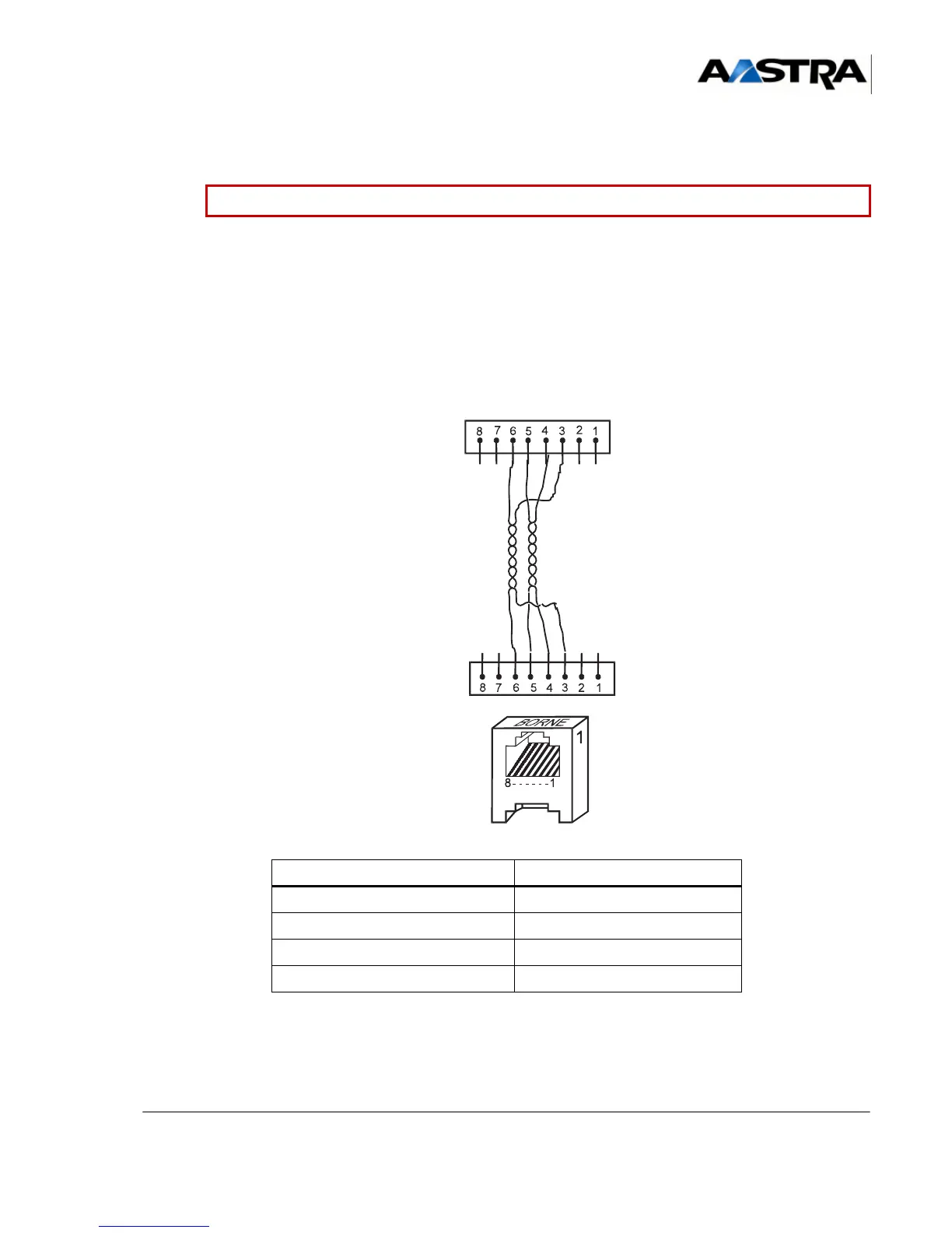
Figure 4.38 C
ONNECTING A DECT BASE STATION TO AN LD4 CARD
TABLEAU 4.38 S0 INTERFACE LINK WITH DECT BASE STATION
Caution: Never invert the polarities of the clock and transmit/receive pairs.
LD4 card RJ45 connector Base station RJ45 connector
Pin 6 (NRD) Pin 6
Pin 3 (RD) Pin 3
Pin 5 (NED) Pin 5
Pin 4 (ED) Pin 4
 Loading...


