AMT/PTD/PBX/0058/4/6/EN Installation and Maintenance Manual - Aastra 5000
Page 236 01/2011 Description des sous-ensembles
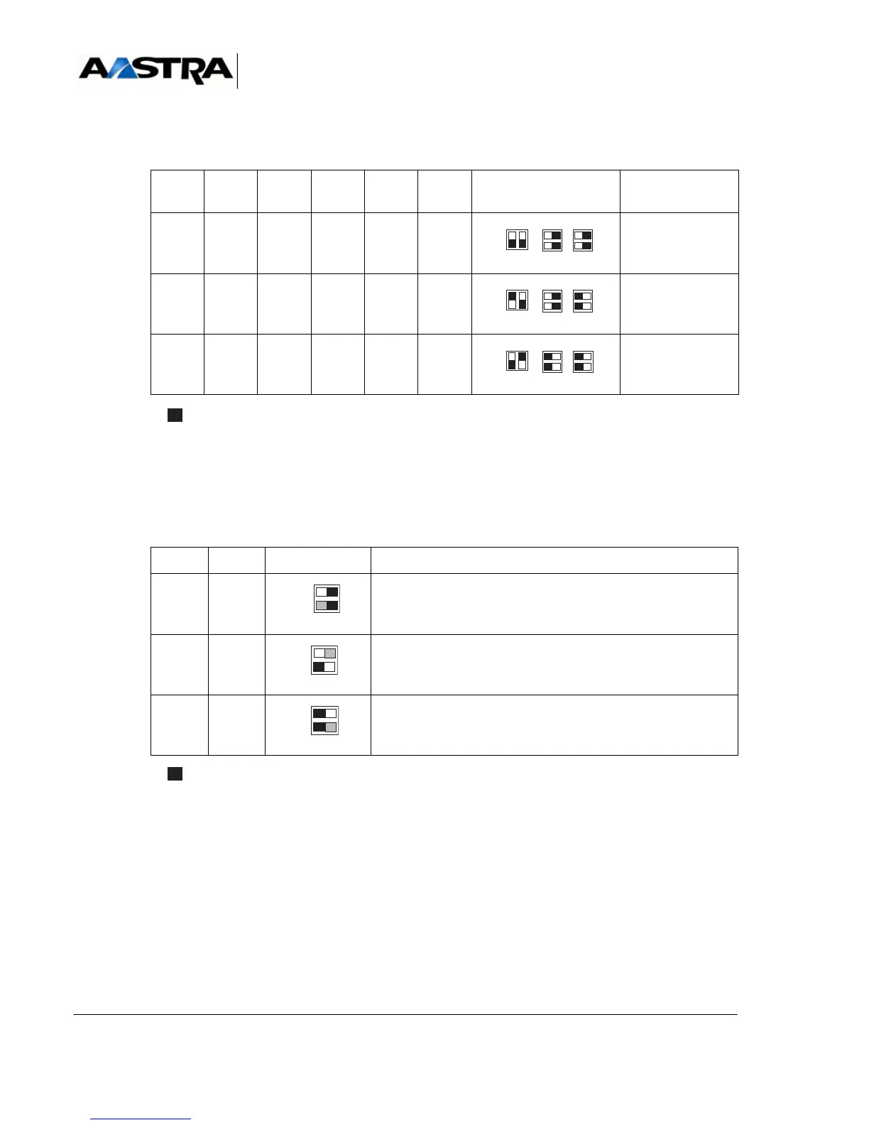
Microswitches CA6, CA3 and CA2 are used to configure line impedance.
* Represents the microswitch.
TABLEAU 4.50 CONFIGURATION OF THE CA6, CA3 AND CA2 MICROSWITCHES
ON THE LT2 CARD
The CA4 microswitch is used to configure the clock and switch the card to programming
mode.
* Represents the microswitch.
TABLEAU 4.51 CONFIGURATION OF THE CA4 MICROSWITCH ON THE LT2 CARD
CA6.1 CA6.2 CA3.1 CA3.2 CA2.1 CA2.2 SWITCH LINE
IMPEDANCE
OFF OFF ON ON ON ON 100 Ω (T1)
ON OFF ON ON OFF OFF 75 Ω (E1)
OFF ON OFF OFF OFF OFF 120 Ω (E1)
CA4.1 CA4.2 SWITCH MODE
OFF OFF Clock signal not used
ON OFF Normal mode - Clock signal used
(factory setting)
ON Programming mode
 Loading...


