AMT/PTD/PBX/0058/4/6/EN Installation and Maintenance Manual - Aastra 5000
Page 188 01/2011 Description des sous-ensembles
4.8.3.1 Installation and wiring
The A0 to A7 interfaces of the EXT1-S card have installation details identical to those of
the interfaces of the LA16X card (see Section 4.14.1.5).
The N0 to N7 interfaces of the EXT1-S card have installation details identical to those of
the interfaces of the LN16X card (see Section 4.14.5.5).
The S/T0 to S/T3 interfaces of the EXT1-S card have installation details identical to those
of the interfaces of the LD4 card for T accesses (see Section 4.13.2.1) but are different for
S accesses.
The T0 and T1 interfaces of the EXT1-S card have installation details identical to those of
the T interfaces of the LD4 card (see section 4.13.2.1).
Wiring DECT base stations
Each base station is connected to an ISDN S0 (BRI) interface of an EXT1-S card, and uses
two pairs: 1 transmit pair and 1 reception pair (refer to document [6] (see Section1.3) for more
information).
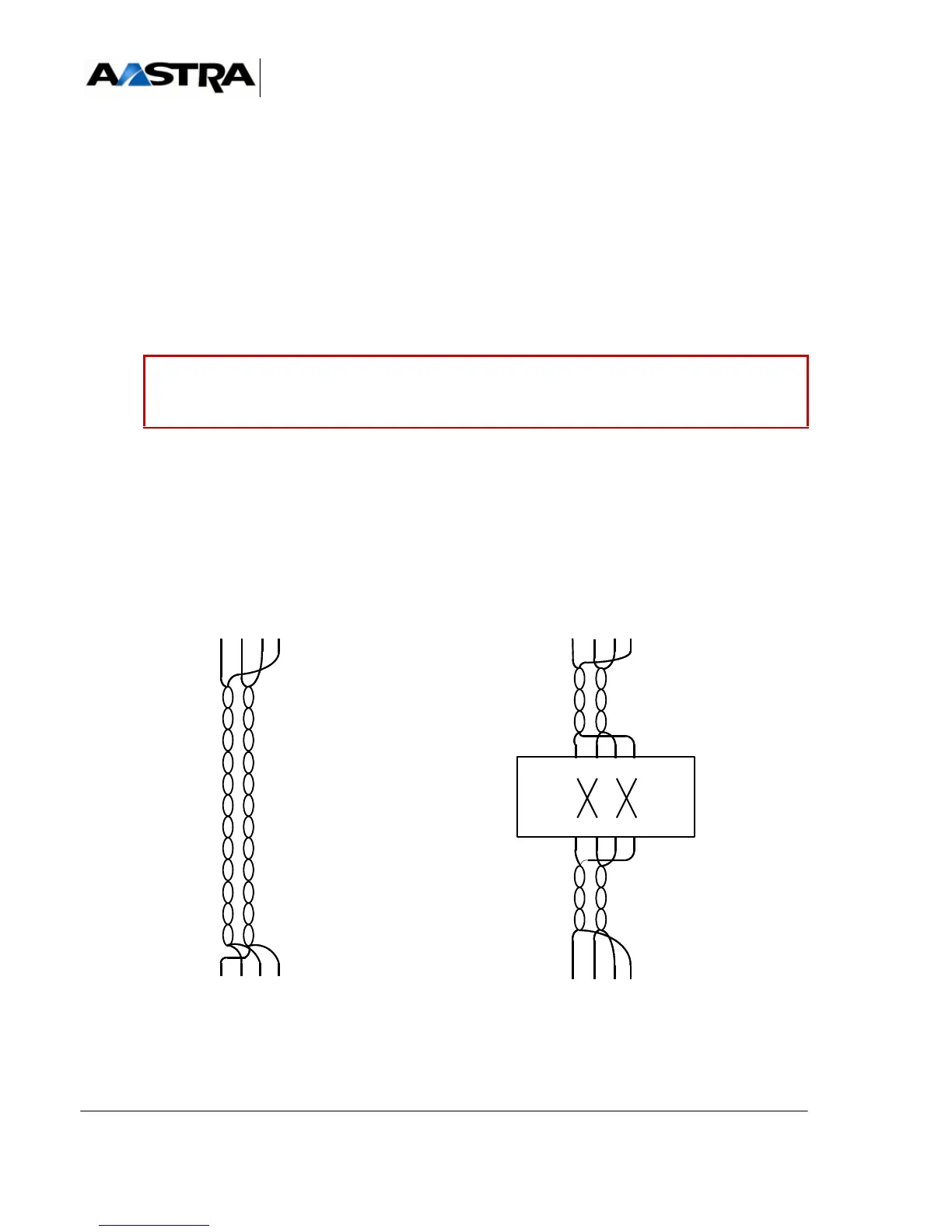
A twisted cable or S0/T0 adaptor is required to connect DECT base stations.
Figure 4.26 CONNECTING A DECT BASE STATION TO AN S0 INTERFACE OF THE EXT1-S CARD
Caution: The S/T accesses of the EXT1-S card are wired in T. To connect S
peripherals (S sets or DECT base stations), a twisted cable or S0/T0
adaptor (see Figure 4.26 ) is, therefore, required.
UCT-S/UCT-C
Borne DECT
Câble croisé
1 ere méthode : utilisation d'un câble croisé 2
eme
méthode : utilisation d'un adaptateur
Câble point à point standard
Boîte de
croisement
Câble point à point standard
P
B
X
_
M
A
T
R
I
X
_
X
S
_
U
C
T
S
_
C
O
N
N
E
X
I
O
N
_
D
E
C
T
_
0
1
_
0
1
324516
7
324516
7 88
324516
7
324516
7 88
324516
78
324516
78
 Loading...


