Installation and Maintenance Manual - Aastra 5000 AMT/PTD/PBX/0058/4/6/EN
Description des sous-ensembles 01/2011 Page 177
4.7.2 Physical description
4.7.2.1 Connectors
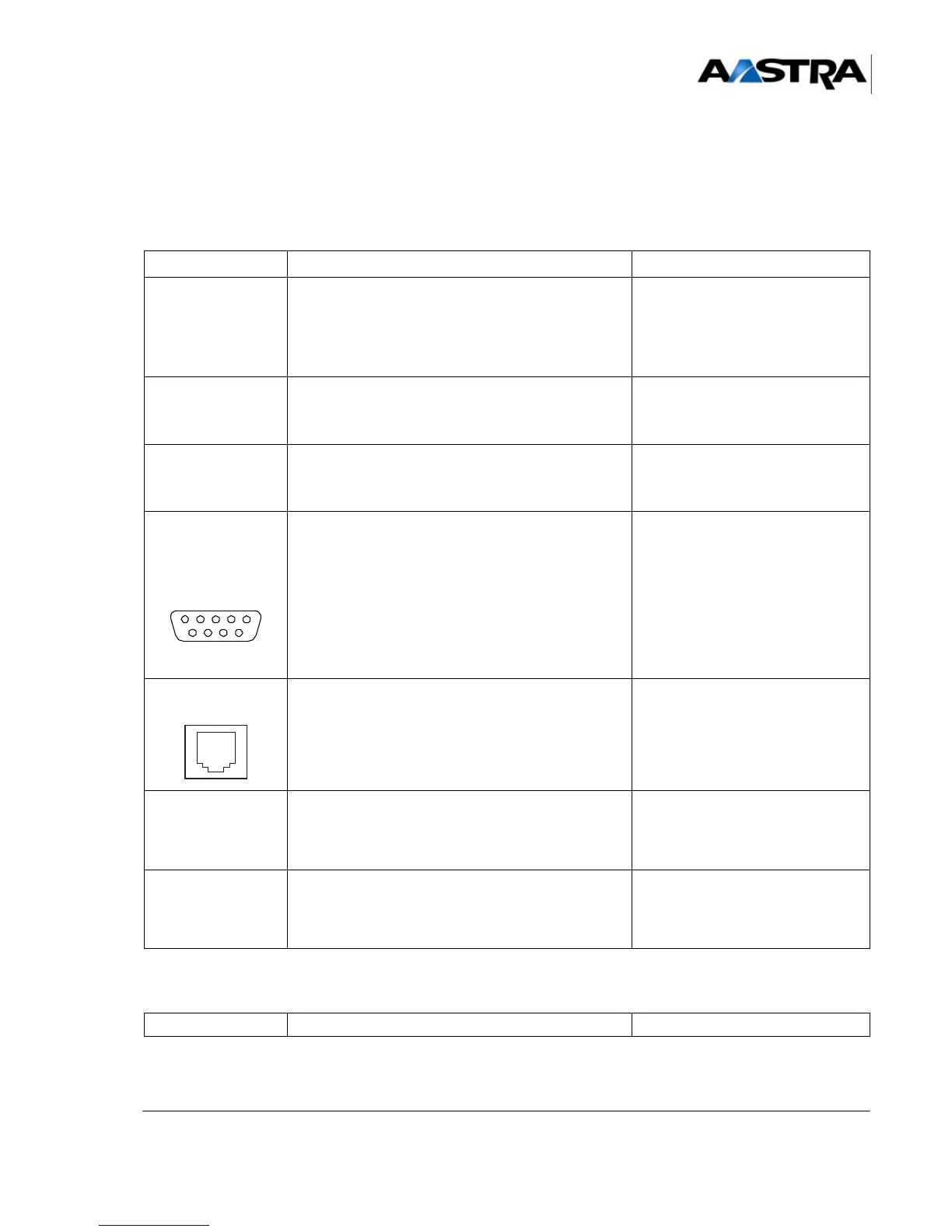
TABLEAU 4.18 DESCRIPTION OF UCV-S CARD CONNECTORS (1/3)
NAME FUNCTIONS/CHARACTERISTICS CONTACTS
J1 (rear panel) Female connector, 192 pins:
• Backplane connection
• Includes the synchronous junctions (equipment
bus) used in the main cabinet, the reference
clocks and system bus.
J2 (rear panel)
Female connector, 48 pins:
link with the RUCV card connector in an expansion
cabinet.
J13 and J14 80-pin CMS connectors: receive two optional
daughter cards - EIP No. 1 on J13 and EIP No.2 on
J14 – to increase the capacity of the VoIP function.
CONSOLE/MODEM
(1)
Caution: Local access to operation in
specific mode
•Pin 1: DCD
•Pin 2: RXC
•Pin 3: TXC
•Pin 4: DTR
•Pin 5: GND
•Pin 6: DSR
•Pin 7: RTS
•Pin 8: CTS
•Pin 9: RI
PRINTER
(1)
Not used.
Note:
•
USB (A)
(1)
USB connector in HOST mode • Pin 1: PWR0
•Pin 2: DNEG0
• Pin 3: DPOS0
•Pin 4: GND
USB (A)
(1)
USB connector in HOST mode • Pin 1: PWR1
•Pin 2: DNEG1
• Pin 3: DPOS1
•Pin 4: GND
NAME FUNCTIONS/CHARACTERISTICS CONTACTS
 Loading...


