Installation and Maintenance Manual - Aastra 5000 AMT/PTD/PBX/0058/4/6/EN
Description et caractéristiques d’un PBX 01/2011 Page 83
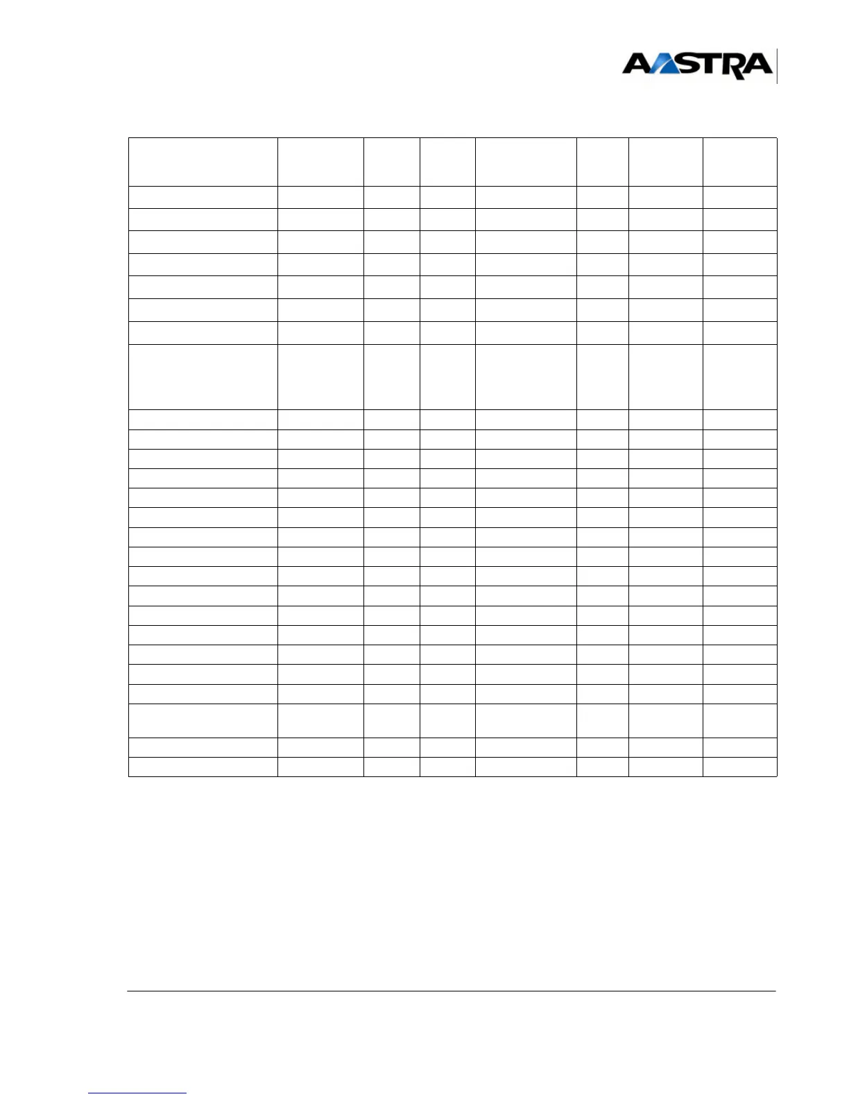
TABLEAU 3.3 LIST OF THE SUB-ASSEMBLIES IN AXL, AXS, AXS12 AND AXS6
IPBXS
(1) If this figure is reached: equipment cards cannot be added.
if the number of CLX cards is below 10: any equipment card can be added.
(2) The total number of LD4, LD4N, LD4X, IPS, PT2 and LT2 cards is ≤10.
(3) The LD4, LD4N, LD4X and LT2 synchronising cards must be located in slots 0 to 5 of the AXL main cabinet when
they are to be used to provide the carrier (RTCP) reference clocks for the main card.
(4) 1 IPS card maximum per system.
UCV
111 1 11 1
RUCV
12 1
CLX cards
10
1
10
1
10
1
3333
LD4/LD4N
(2) (3)
666 3 33 3
LD4X
(2) (3)
10 10 10 3 3 3 3
LT2
(2) (3)
666 1 11 1
IPS
(2)(4)
111 1 11 1
PT2
(2)
+ 8-channel VoIP4E
+ 16-channel VoIP4E
+ 32-channel VoIP4E
444 1 11 1
CS1 444 3 33 3
CA1 333 3 33 3
CP1 888 3 33 3
MUM 10 10 10 3 3 3 3
Equipment cards 12 26 40 3 6 3 3
LA16X 12 26 40 3 6 3 3
LA16X-8 12 26 40 3 6 3 3
LA8 12 12 12 3 6 3 3
LN16X 12 26 32 3 6 3 3
LN16X-8 12 26 32 3 6 3 3
LN8 12 12 12 3 6 3 3
LM8 12 12 12 3 6 3 3
LH8 12 12 12 3 6 3 3
LH16X 12 26 40 3 6 3 3
LH16X-8 12 26 40 3 6 3 3
LR4
LR4-DTOC
12 12 12 3 6 3 3
LI1 12 12 12 3 6 3 3
BTX 111 1 11 1
SUBASSEMBLIES AXL
Main Cabinet
A2XL A3XL AXS
Cabinet
Main
A2XS AXS12 main
cabinet
AXS6 main
cabinet
 Loading...


