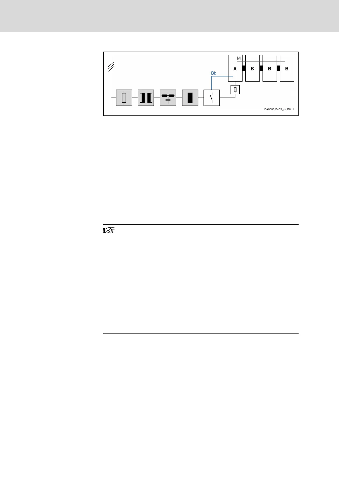
Components marked with gray background color: Optional, de‐
pending on the application
A Component HCS01 (more powerful than component B); con‐
nected to other components via DC bus
B Component HCS01 (less powerful than component A); connec‐
ted to other components via DC bus
Bb Bb relay contact wiring
M Module bus
Fig. 4-30: Central Supply
Group supply and DC bus coupling
DC bus coupling options
For group supply with DC bus coupling, there are two options:
1. At least two devices supply the DC bus and other devices are supplied
via th common DC bus connection
2. All devices with common DC bus connection supply the DC bus
When sizing the devices for group supply, observe the balancing
factor:
● 0.8 (if balancing is used)
● 0.5 (if balancing is not used)
With group supply, the Bb relay contacts of all supplying devices
have to be connected in series. This guarantees that the mains
contactor is switched off in the case of error in a device.
The DC bus coupling lines should not be run outside of the con‐
trol cabinet. The maximum line length of a DC bus coupling is
2 m. See also description of the connection point X77 for more in‐
formation (chapter "X77, L+ L-, DC Bus Connection" on page
151).
Balancing: To distribute the charging process of the DC bus equally over all
supplying devices, balancing chokes or balancing resistors have to be instal‐
led in the supply feeder.
Balancing choke
● HCS01.1E-W0028: Mains choke HNL01.1E-1000-N0012-A-500-NNNN
● HCS01.1E-W0054: Mains choke HNL01.1E-0600-N0032-A-500-NNNN
The firmware provides for the balancing of the power over all braking resis‐
tors. See also the documentation of the firmware used (parameter "P-0-0860,
Converter configuration").
Bosch Rexroth AG DOK-INDRV*-HCS01******-PR05-EN-P106/341
Rexroth IndraDrive CsDrive Systems with HCS01
Combining the individual components
 Loading...


