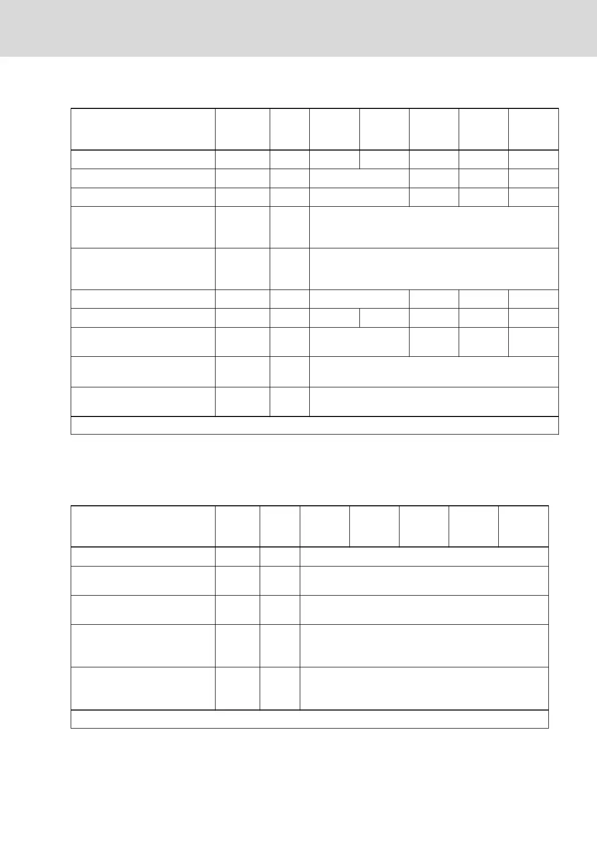
Integrated braking resistor data
Description Symbol Unit
HCS01.1E
-W0005-
_-03
HCS01.1E
-W0008-
_-03
HCS01.1E
-W0018-
_-03
HCS01.1E
-W0028-
_-03
HCS01.1E
-W0054-
_-03
Braking resistor continuous power
P
BD
kW 0.02 0.03 0.05 0.15 0.50
Braking resistor peak power
P
BS
kW 4.00 7.20 10.60 25.80
Nominal braking resistor
R
DC_Bleeder
ohm 180 100 68 28
Braking resistor switch-on thresh‐
old - independent of mains volt‐
age
1)
U
R_DC_On_f
V 820
Braking resistor switch-on thresh‐
old - depending on mains volt‐
age
2)
U
R_DC_On_v
130% of parameter P-0-0815, 820V at most
Maximum allowed on-time duty
t
on_max
s 0.20 0.32 0.28 0.50
Minimum allowed cycle time
T
cycl
s 40.00 26.70 45.40 20.00 26.00
Regenerative power to be absor‐
bed
W
R_max
kWs 0.80 2.25 3.00 13.00
Balancing factor for P
BD
(for paral‐
lel operation at common DC bus)
f 0.80
Cooling of integrated braking re‐
sistor
Forced ventilation
Last modification: 2012-05-16
1) 2) Factory setting
Tab. 7-47: HCS - Integrated braking resistor data
7.3.5 Inverter
Power section data - inverter
Description Symbol Unit
HCS01.1E
-W0003-
_-02
HCS01.1E
-W0006-
_-02
HCS01.1E
-W0009-
_-02
HCS01.1E
-W0013-
_-02
HCS01.1E
-W0018-
_-02
Allowed switching frequencies
1)
f
s
kHz 4, 8, 12, 16
Output voltage, fundamental wave
for V/Hz (U/f) control
V
out_eff
V ~UDC x 0.71
Output voltage, fundamental wave
for closed-loop operation
V
out_eff
V ~UDC x 0.71
Rise of voltage at output with
U
LN_nenn
and 15 m motor cable
length phase-phase (10-90%)
2)
dv/dt kV/µs 5.00
Rise of voltage at output with
U
LN_nenn
and 15 m motor cable
length phase-ground (10-90%)
3)
dv/dt kV/µs 5.00
Last modification: 2015-06-12
DOK-INDRV*-HCS01******-PR05-EN-P Bosch Rexroth AG 243/341
Rexroth IndraDrive CsDrive Systems with HCS01
Technical data of the components
 Loading...


