6.2.4 Optional connection points
X8, Optional Encoder (Option EC)
You can connect an optional encoder to connection point X8.
Technical data: See description of connection point X4.
X8, Encoder Emulation (Option EM)
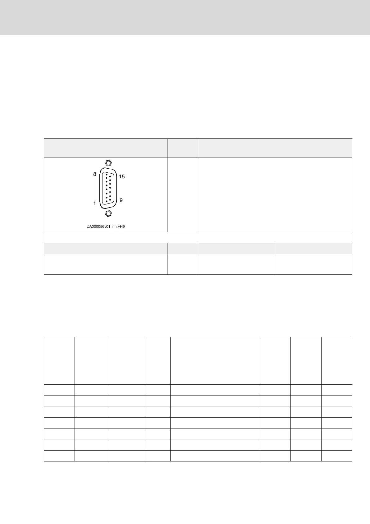
Description
Emulation of absolute value and incremental encoder signals for further eval‐
uation by a control unit. The signals are galvanically isolated from the circuit
board.
View Identifica‐
tion
Function
X8 Encoder emulation
D-Sub 15-pin, male Unit Min. Max.
Connection cable
Stranded wire
mm
2
0,25 0,5
Tab. 6-22: Function, Pin Assignment, Properties
Emulated Encoder Systems
● Incremental encoder
● SSI encoder
● Incremental encoder with signal level converter
Pin Assignment
Connec‐
tion
Signal Level Input/
Output
Function Incremen‐
tal encod‐
er
SSI en‐
coder
Incremen‐
tal encod‐
er with
signal lev‐
el convert‐
er
1 n. c. - - Not assigned
2 UL 5 … 30 V In Power supply for output driver ✓
3 SSI_CLK+ RS422 In SSI clock positive ✓
4 SSI_CLK- RS422 In SSI clock negative ✓
5 n. c. - - Not assigned
6 ULA0 UL Out Reference track with UL level ✓
7 ULA1 UL Out Track A1 with UL level ✓
DOK-INDRV*-HCS01******-PR05-EN-P Bosch Rexroth AG 159/341
Rexroth IndraDrive CsDrive Systems with HCS01
Mounting and installation
 Loading...


