Mounting Positions of Components
Risk of damage to the components!
Only operate the components in their allowed mounting positions.
Allowed Mounting Position of the
Components
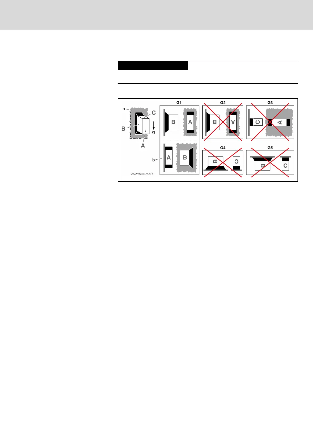
Only the mounting position G1 is allowed for HCS01 components.
A, B, C Sides of a component: A = front side, B = left or right side,
C = top side
a Mounting surface in control cabinet
b Mounting position G1, when side B of component directly
mounted to mounting surface
g Direction of gravitational force
G1 Normal mounting position: The natural convection supports the
forced cooling air current. This avoids the generation of pock‐
ets of heat in the component.
G2 180° to normal mounting position
G3 90° to normal mounting position
G4 Bottom mounting; mounting surface on bottom of control cabi‐
net
G5 Top mounting; mounting surface at top of control cabinet
Fig. 4-11: Allowed Mounting Position of the Components
DOK-INDRV*-HCS01******-PR05-EN-P Bosch Rexroth AG 67/341
Rexroth IndraDrive CsDrive Systems with HCS01
Combining the individual components
 Loading...


