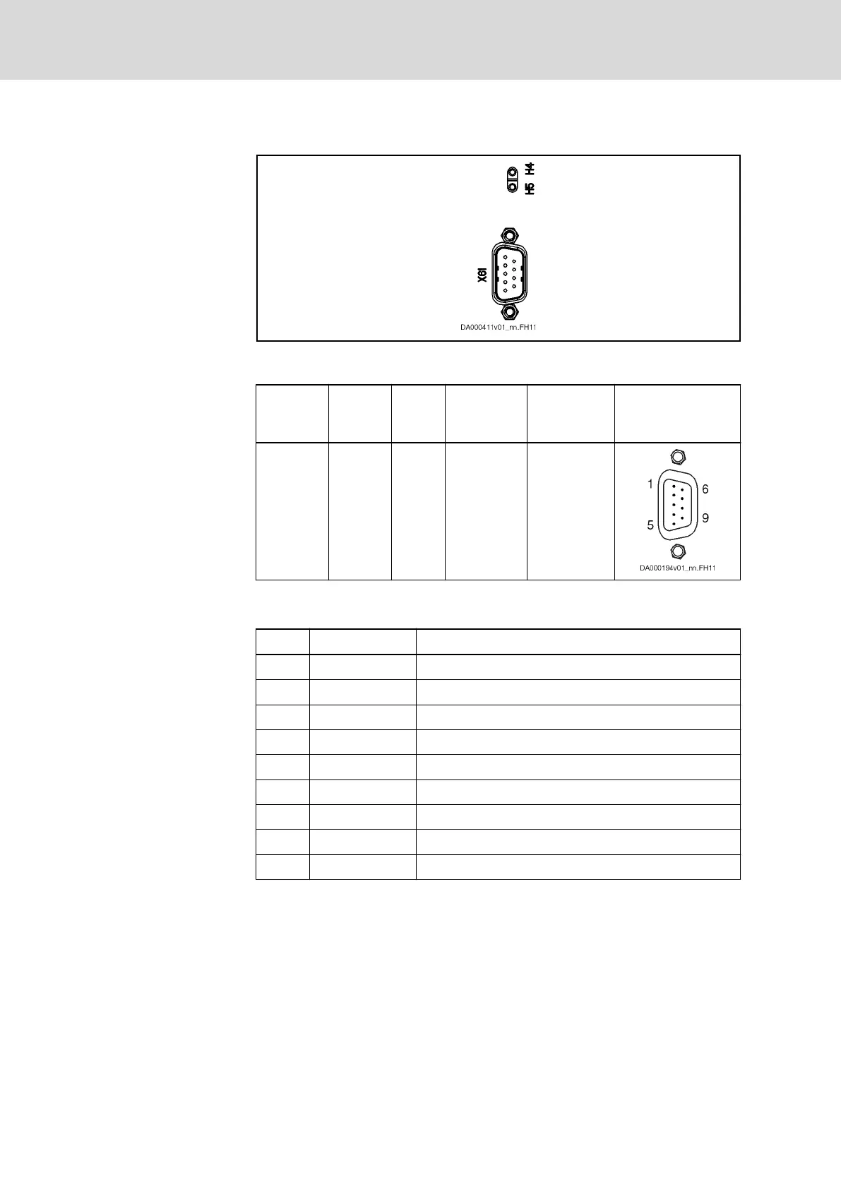
X61, CANopen (CN Option)
Description
Fig. 6-22: CANopen
Connection Point
Connec‐
tion point
Type Num‐
ber of
poles
Type of de‐
sign
Stranded wire
[mm²]
Figure
X61 D-Sub 9 Pins on de‐
vice
0,25-0,5
Tab. 6-32: Connection point
Pin Assignment
Pin Signal Function
1 n. c. -
2 CAN-L Negated CAN signal (Dominant Low)
3 CAN-GND Reference potential of CAN signals
4 n. c. -
5 Drain/Shield Shield connection
6 GND Reference potential of device
7 CAN-H Positive CAN signal (Dominant High)
8 n. c. -
9 n. c. -
Tab. 6-33: Signal Assignment
Technical Data
chapter 7.1.5 "CN - CANopen" on page 215
Bosch Rexroth AG DOK-INDRV*-HCS01******-PR05-EN-P170/341
Rexroth IndraDrive CsDrive Systems with HCS01
Mounting and installation
 Loading...


