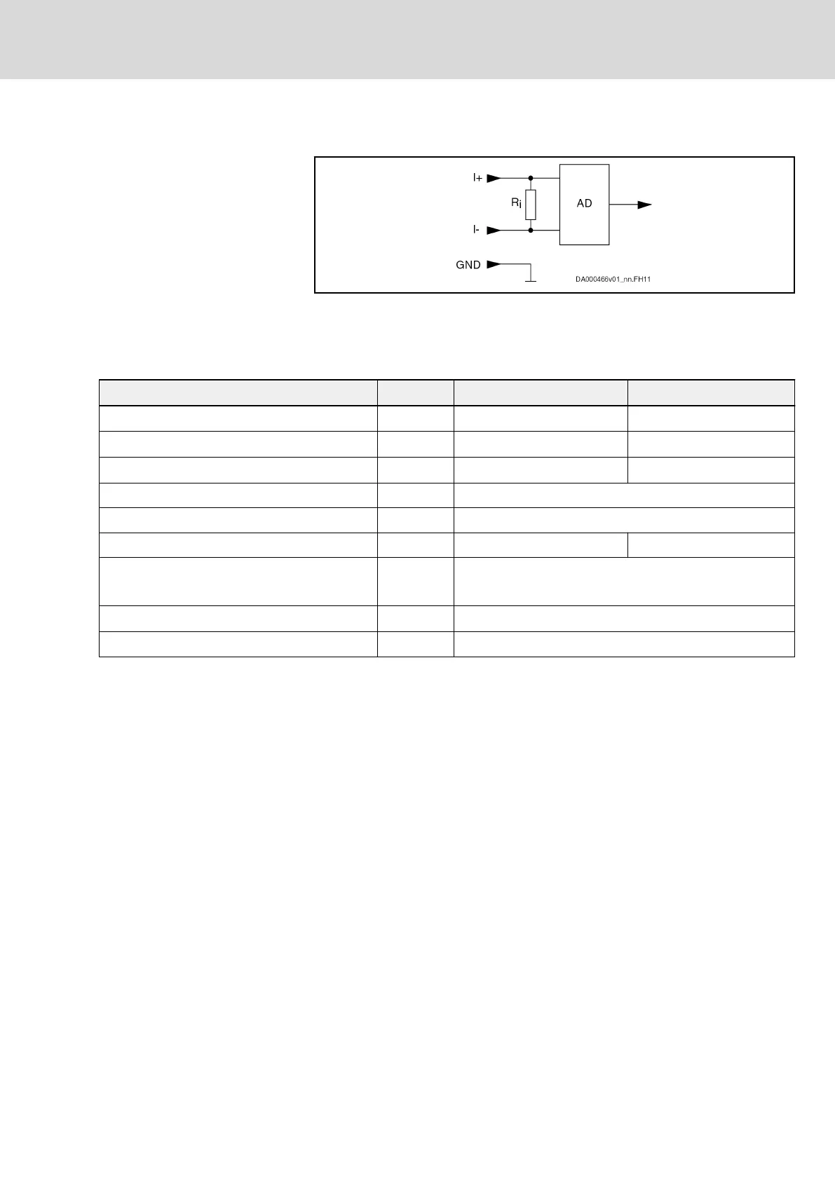
7.1.9 Analog current input
AD Analog/digital converter
Fig. 7-33: Analog current input
Electrical data (current inputs [-20/4 … 20 mA])
Spring terminal (connector) Unit min. max.
Input current measuring range
1)
mA -20 / 4 20
Input current minimum value monitoring
2)
mA 2 3
Input current maximum value monitoring
3)
mA 21 22
Input resistance Ω 280
Input bandwidth (-3db) kHz 1.3
Relative measuring error at 18 mA % -1 +1
Resolution -
13bit (12bit + 4-fold oversampling)
5)
12bit (11bit + 4-fold oversampling)
6)
Overload protection
4)
- Present
Wiring - Only use shielded cables for cable lengths > 30 m.
1) Measuring range (-20 … 20 or 4 … 20) can be set using a pa‐
rameter. With a measuring range 4 … 20, the minimum value
monitoring (wire break) is automatically active.
2) Only possible with a measuring range 4 … 20
3) Monitoring switched off at approx. ±35 mA
4) In the case of input currents greater than the maximum value,
an error is signaled and the input is switched at high resistance
5) Applies to: Optional I/O extension DA (X38)
6) Applies to: Control sections with extended scope CSx02.1B
(X35), CDB02.1B (X36)
Tab. 7-37: Electrical data
DOK-INDRV*-HCS01******-PR05-EN-P Bosch Rexroth AG 227/341
Rexroth IndraDrive CsDrive Systems with HCS01
Technical data of the components
 Loading...


