View Identifica‐
tion
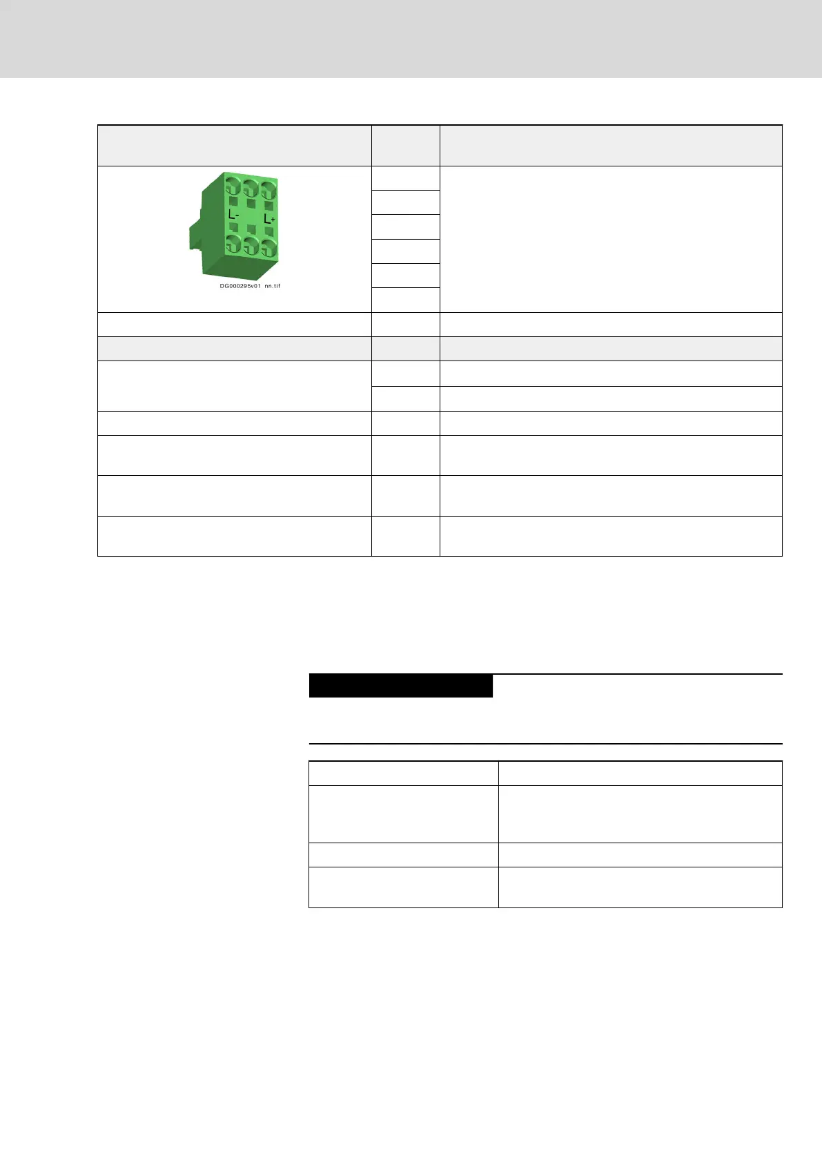
Function
L- Connection points for connecting DC bus connections of
several devices
(The DC bus connector is available as an accessory; see
chapter 8.2.2 "DC Bus Connector (RLS0778/K06)" on page
258)
L-
n. c.
n. c.
L+
L+
Unit
Maximum connection cross section (stranded
wire)
mm
2
6
AWG 8
Stripped length mm 15
Short circuit protection Via fusing elements connected in the incoming circuit to the
mains connection
Overload protection Via fusing elements connected in the incoming circuit to the
mains connection
Maximum current carrying capacity "looping
through" from L+ to L+, L- to L-
A 31
Tab. 6-19: Function, Pin Assignment, Properties
Notes on Installation
To wire the DC bus, use the shortest possible flexible, twisted wires.
When the DC buses of several devices have been coupled, the lines mustn't
be run outside of the control cabinet.
Risk of damage by reversing the polarity of
the DC bus connections L- and L+
Make sure the polarity is correct.
Length of twisted wire Max. 2 m
Line cross section
Min. 6 mm
2
,
but not smaller than cross section of supply feed‐
er
Line protection By means of fuses in the mains connection
Dielectric strength of single
strand against ground
≥ 750 V (e.g.: strand type - H07)
Tab. 6-20: DC Bus Line
DOK-INDRV*-HCS01******-PR05-EN-P Bosch Rexroth AG 153/341
Rexroth IndraDrive CsDrive Systems with HCS01
Mounting and installation
 Loading...


