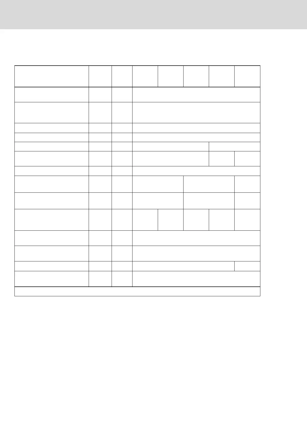
Temperatures, cooling, power dissipation, distances
Cooling and power dissipation data
Description Symbol Unit
HCS01.1E
-W0003-
_-02
HCS01.1E
-W0006-
_-02
HCS01.1E
-W0009-
_-02
HCS01.1E
-W0013-
_-02
HCS01.1E
-W0018-
_-02
Ambient temperature range for
operation with nominal data
T
a_work
°C 0...40
Ambient temperature range for
operation with reduced nominal
data
T
a_work_red
°C 0...55
f
Ta
%/K 2.0
Allowed mounting position G1
Cooling type Not ventilated Forced ventilation
Volumetric capacity of forced cool‐
ing
V
m
3
/h
- 11.00 56.00
Allowed switching frequencies
1)
f
s
kHz 4, 8, 12, 16
Power dissipation at I
out_cont
= 0 A;
f
s
= f
s
(min.)
2)
P
Diss_0A_fs
min
W 4 6 8
Power dissipation at I
out_cont
= 0 A;
f
s
= f
s
(max.)
3)
P
Diss_0A_fs
max
W 15 17 21
Power dissipation at continuous
current and continuous DC bus
power respectively
4)
P
Diss_cont
W 8.00 10.00 12.00 20.00 70.00
Minimum distance on the top of
the device
5)
d
top
mm 90
Minimum distance on the bottom
of the device
6)
d
bot
mm 90
Horizontal spacing on the device
7)
d
hor
mm 10 0
Temperature increase with mini‐
mum distances d
bot
; d
top
; P
BD
ΔT K tbd
Last modification: 2015-06-12
1) Also depending on firmware and control section; see parame‐
ter description "P-0-0001, Switching frequency of power output
stage"; see "P-0-4058, Amplifier type data"
2) 3) Plus dissipation of braking resistor and control section; find in‐
terim values by interpolation to P_Diss_cont
4) Plus dissipation of braking resistor and control section
5) 6) 7) See fig. "Air intake and air outlet at device"
Tab. 4-19: HCS - Data for cooling and power dissipation
Bosch Rexroth AG DOK-INDRV*-HCS01******-PR05-EN-P64/341
Rexroth IndraDrive CsDrive Systems with HCS01
Combining the individual components
 Loading...


