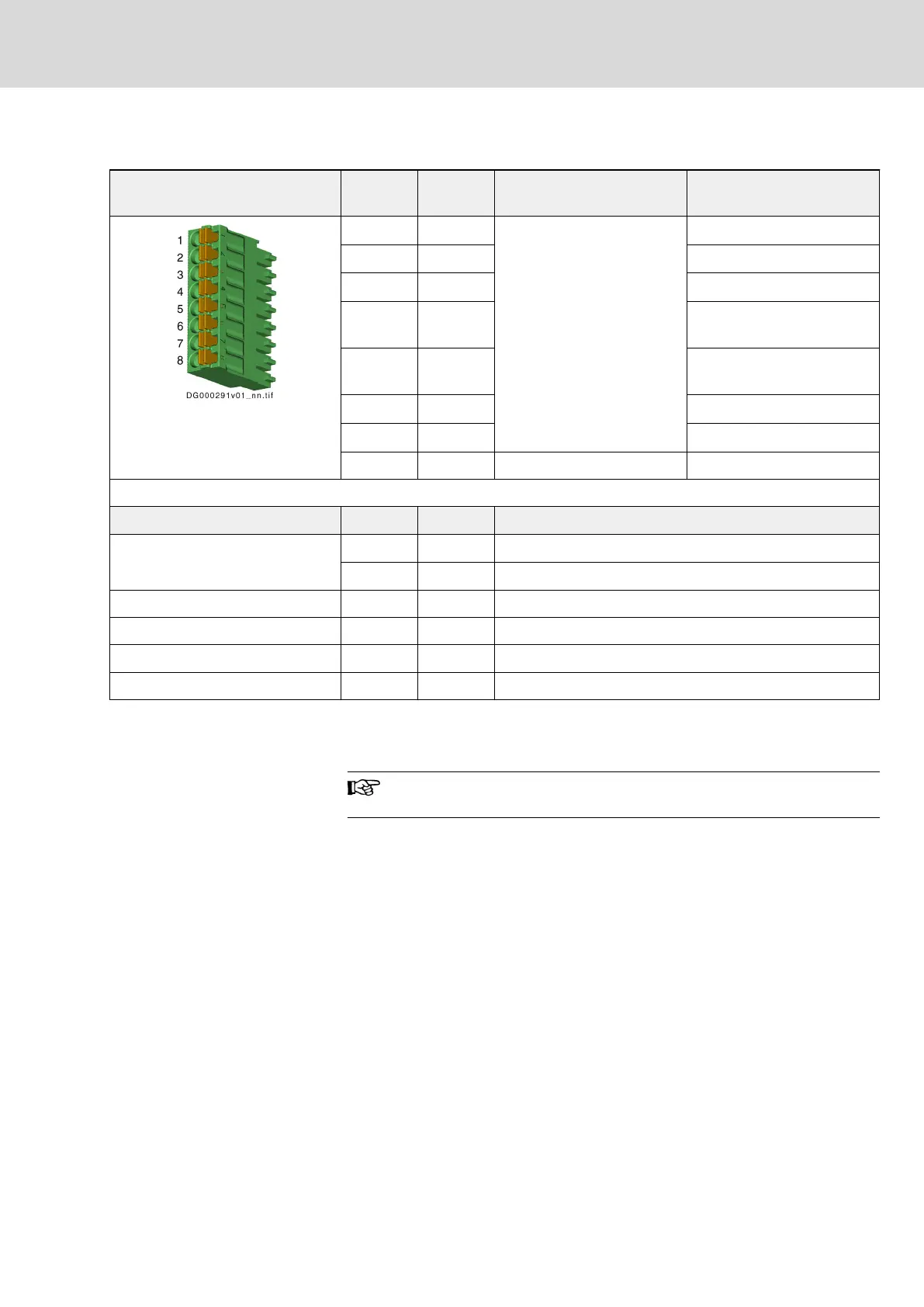
X31, Digital Inputs, Digital Output
View Connec‐
tion
Signal
name
Function Default assignment
1 I_1 Digital input
Probe 1
1)
2 I_2
Probe 2
1)
3 I_3
E-Stop input
2)
4 I_4 Travel range limit switch in‐
put
2)
5 I_5 Travel range limit switch in‐
put
2)
6 I_6
Not assigned
2)
7 I_7
Not assigned
2)
8 I/O_8 Digital input/output Not assigned
Spring terminal (connector) Unit Min. Max.
Connection cable
Stranded wire
mm
2
0,2 1,5
AWG 24 16
Stripped length mm - 10
Input current A - 0,01
Input voltage V - 24
Output current I/O_8 A - 0,5
1) Digital Inputs Type B (Probe)
2) Digital Inputs Type A (Standard)
Tab. 6-15: Function, Pin Assignment, Properties
The reference potential for the digital inputs and the digital input/
output is applied to X13.1 and X13.2.
Technical Data
● chapter "Digital Inputs Type A (Standard)" on page 218
● chapter "Digital inputs type B (probe)" on page 219
● chapter "Digital Outputs (Standard)" on page 222
DOK-INDRV*-HCS01******-PR05-EN-P Bosch Rexroth AG 147/341
Rexroth IndraDrive CsDrive Systems with HCS01
Mounting and installation
 Loading...


