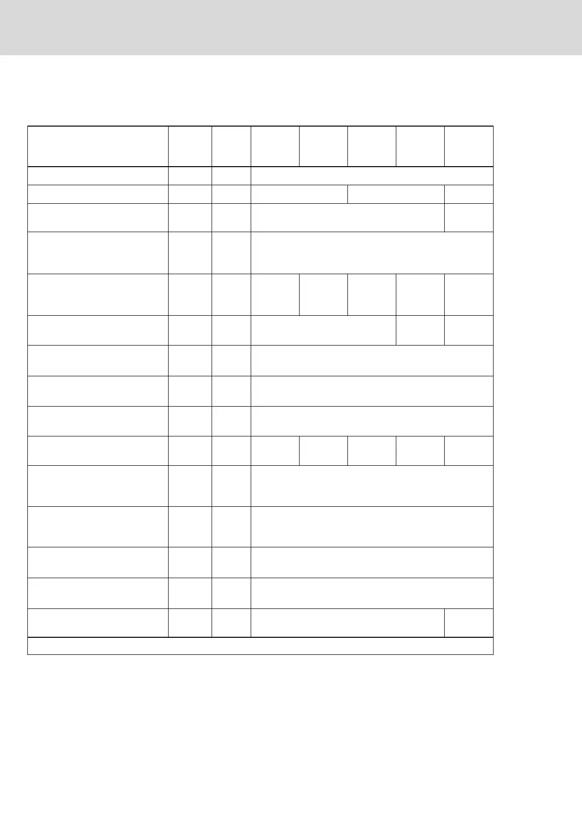
7.3.3 DC bus
Power section data - DC bus
Description Symbol Unit
HCS01.1E
-W0003-
_-02
HCS01.1E
-W0006-
_-02
HCS01.1E
-W0009-
_-02
HCS01.1E
-W0013-
_-02
HCS01.1E
-W0018-
_-02
DC bus voltage
U
DC
V
U
LN
x 1.41
Capacitance in DC bus
C
DC
mF 0.44 0.78 1.20
DC resistance in DC bus (L+ to
L-)
R
DC
kOhm 663.00 61.20
Rated power (t > 10 min) at f
s
= 4
kHz; U
LN_nenn
; control factor a
0
>
0.8; with mains choke
P
DC_cont
kW -
Rated power (t > 10 min) at
f
s
= 4 kHz; U
LN_nenn
; control factor
a
0
> 0.8; without mains choke
P
DC_cont
kW 0.15 0.25 0.46 0.80 1.80
Factor to reduce P
DC_cont
at single-
phase mains voltage
f
1_3ph
1.00 0.80 0.70
P
DC_cont
and P
DC_max
vs. mains in‐
put voltage; U
LN
≤ U
LN_nenn
%/V
P
DC_cont (ULN)
= P
DC_cont
x [1 - (230 - U
LN
) x 0.0025]
P
DC_cont
and P
DC_max
vs. mains in‐
put voltage; U
LN
> U
LN_nenn
%/V No power increase
Maximum allowed DC bus power
at U
LN_nenn
; with mains choke
P
DC_max
kW -
Maximum allowed DC bus power
at U
LN_nenn
; without mains choke
P
DC_max
kW 0.45 0.75 1.38 2.40 4.80
Balancing factor for P
DC_cont
(for
parallel operation at common DC
bus) with mains choke
-
Balancing factor for P
DC_cont
(for
parallel operation at common DC
bus) without mains choke
-
Monitoring value maximum DC
bus voltage, switch-off threshold
U
DC_lim‐
it_max
V 420
Monitoring value minimum DC bus
voltage, undervoltage threshold
U
DC_lim‐
it_min
V
0.75 x U
LN
or "P-0-0114, Undervoltage threshold", if
P-0-0114 > 0.75 x U
LN
Charging resistor continuous pow‐
er
P
DC_Start
kW 0.03 0.15
Last modification: 2012-05-16
Bosch Rexroth AG DOK-INDRV*-HCS01******-PR05-EN-P240/341
Rexroth IndraDrive CsDrive Systems with HCS01
Technical data of the components
 Loading...


