Ideally, the motor power cables should exit the control cabinet at a distance
of at least d3 = 200 mm from the (filtered) power supply cable.
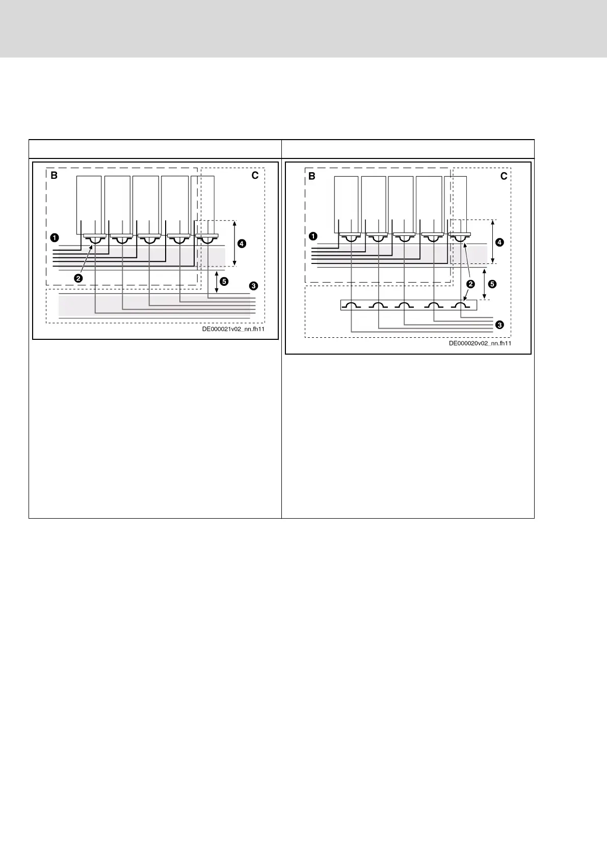
Converter - routing motor power cables
With cable duct Without cable duct
B Area B
C Area C
1 Cable duct for mains connection lines
2 Shield connection of motor power cable with
clips at least at one point; alternatively, at
the device or control cabinet mounting plate
3 Cable duct for motor power cables
4 Parallel routing of mains connection lines
and motor power cables over a maximum of
300 mm
5 Distance of at least 100 mm or separated by
a grounded distance plate
Fig. 6-24: Routing motor power cables with cable
duct
B Area B
C Area C
1 Cable duct for mains connection lines
2 Shield connection of motor power cable with
clips at least at one point; alternatively, at
the device or control cabinet mounting plate
3 Control cabinet outlet of motor power cables
4 Parallel routing of mains connection lines
and motor power cables over a maximum of
300 mm
5 Distance of at least 100 mm or separated by
a grounded distance plate
Fig. 6-25: Routing motor power cables without cable
duct
Tab. 6-34: Routing converter cables
Ground connections
Housing and mounting plate
It is possible to avoid the emission of interference with proper ground connec‐
tions because interference is discharged to ground through the most direct
route.
Ground connections of the metal housings for EMC-critical components (such
as filters, devices of the drive system, connection points of the cable shields,
devices with microprocessor and switching power supply units) have to be
solidly contacted over a large surface area. This also applies to all screw con‐
nections between mounting plate and control cabinet wall and to mounting a
ground bar to the mounting plate.
The best solution is to use a zinc-coated mounting plate. Compared to a var‐
nished plate, the connections in this case have good long-term stability.
Connection elements
For varnished mounting plates, always use screw connections with tooth lock
washers and zinc-coated, tinned screws as connection elements. At the con‐
nection points, remove the varnish so that there is safe electrical contact over
a large surface area. Achieve contact over a large surface area using bare
connection surfaces or several connection screws. For screw connections,
Bosch Rexroth AG DOK-INDRV*-HCS01******-PR05-EN-P178/341
Rexroth IndraDrive CsDrive Systems with HCS01
Mounting and installation
 Loading...


